Stretch Tuning

I’m waiting for parts before I can proceed with the Seventy Three so I thought I’d use the time to try retuning my Fifty Four. According to the Service Manual, Rhodes pianos are tuned to equal temperament at the factory – each note is tuned to its theoretically correct frequency. I’m not certain why that is as I don’t think there’s much question that stretch tuning is more appropriate. I’ve never fully understood the theory behind stretch tuning so I’ll leave it to Wikipedia to provide the back story.

I’ve heard more than once that Rhodes pianos are notorious for going out of tune. Even though mine spent more than a few years being moved around on a regular basis, I guess it’s led a relatively sheltered life. In all the years I’ve owned it, I don’t think I’ve ever adjusted the tuning and according to my tuner, the tines haven’t moved very far off their targets.

Generally, the pitch of a particular note is determined by the size of the tone bar and length of the tine. By themselves though, the tone bar and tine are engineered to produce a pitch somewhere only in the neighborhood of the desired value, give or take a half step. To get the rest of the way, little springs are wrapped around the tines. The pitch can be fine-tuned by sliding the springs along the length of the tine. Making this adjustment can be tricky business though and I went through a few different ideas trying to find the easiest approach.

Perhaps the most interesting attempt involved a Dremel engraver. I chucked a modified screwdriver into the tool thinking maybe the reciprocating vibrations it produced might help move the springs in a controlled manner. It actually worked to a degree but was a pain to use and not really worth the effort.

Vintage Vibe sells a standard tack puller as a tuning tool. The angle on the end allows you to reach around the tone bar and the notch cut in the end helps to catch the spring. I found it hard to control the adjustments I was making, particularly on the higher notes where smaller and smaller movements are required to make the same pitch adjustments. For a while, I tried using a small hammer to tap the tool’s handle as it pushed against the spring but it was still too difficult to give it just the right nudge.

There is an alternative to using the keys to sound the notes while adjusting the tuning. The harp assembly is mounted on two arms that, after a few screws are removed, allow it to swing up clear of the hammers and dampers. Even though the hammers can’t reach, the tines remain positioned in front of their pickups and the harp can remain plugged into the amplifier. From here, the tines can be plucked and the springs can be moved by hand. I quickly found that very small adjustments could be made by twisting the springs around the tines while applying just a little pressure in the proper direction. This suddenly made it much easier to get even the treble end locked onto the exact pitches.

Traditionalists tune pianos by ear. They strike a tuning fork and match a note, then finish the keyboard by listening for the ‘beats’ made when two nearly identical wavelengths collide. This involves skills I don’t currently possess and for this job, I availed myself of the Peterson StroboFlip tuner. A strobe tuner is a significant upgrade from regular quartz tuners. Compared to the erratic wanderings of the quartz devices, the stability of the strobe’s display makes it a pleasure to work with. The Peterson also allows a much finer control and wider range of pitch offsets making it easier to use for stretch tuning. I recorded a video of the Peterson at work showing how accurate it allows you to be.

To find the proper offset values to use, I referred to the chart provided by the Rhodes Service Manual. A4 (the A above Middle C) is used as a starting reference and is tuned to the standard 440 Hz. As progress is made away from A4, notes are tuned increasingly further away from their mathematically-correct frequencies. Higher notes are adjusted sharp and lower notes are flattened.

The result of this tuning process should be an instrument that sounds more in tune than one set to an equal temperament tuning. I don’t hear it. I played another take of Recorda-Me after retuning. Comparing this to the same tune recorded before, I can’t tell the difference. On a Seventy Three’s wider scale, the “stretching” would be even more pronounced so maybe I’ll have a greater appreciation when I get one of those tuned up.

Pickups

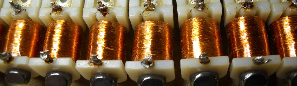
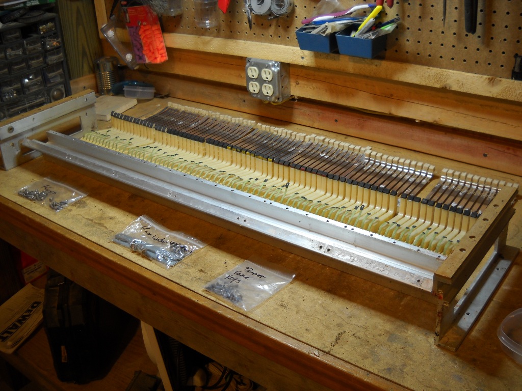
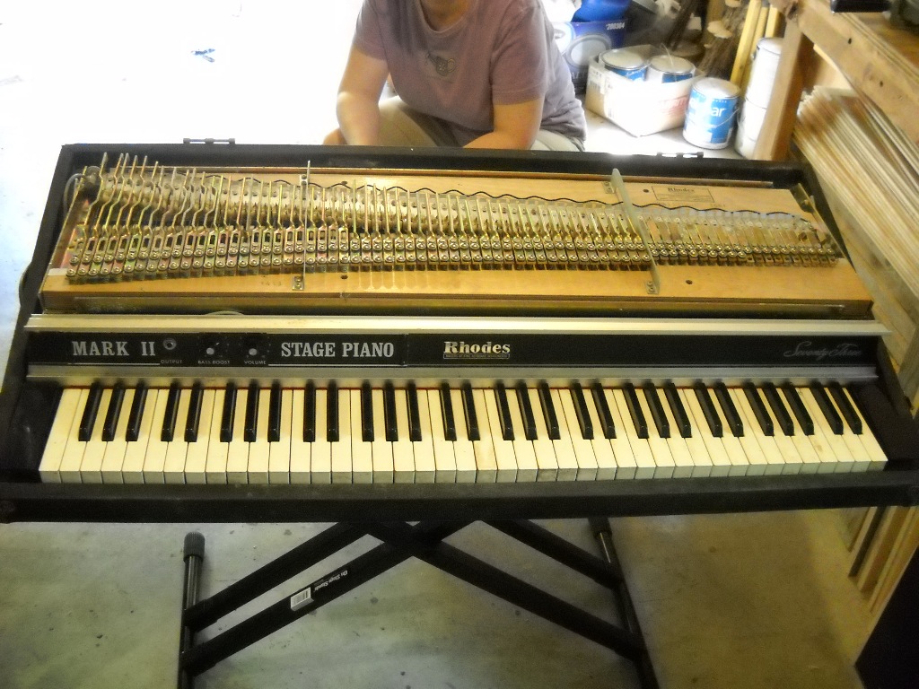
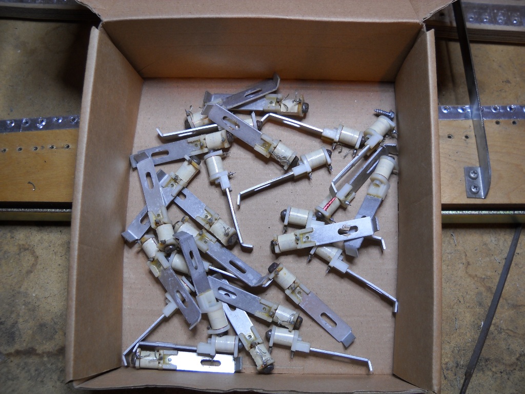
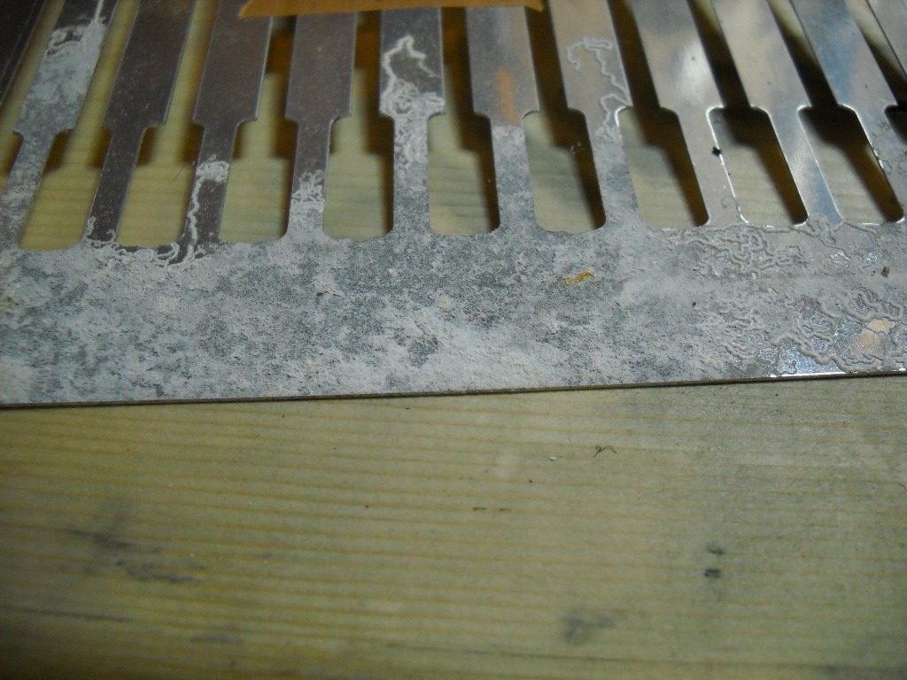
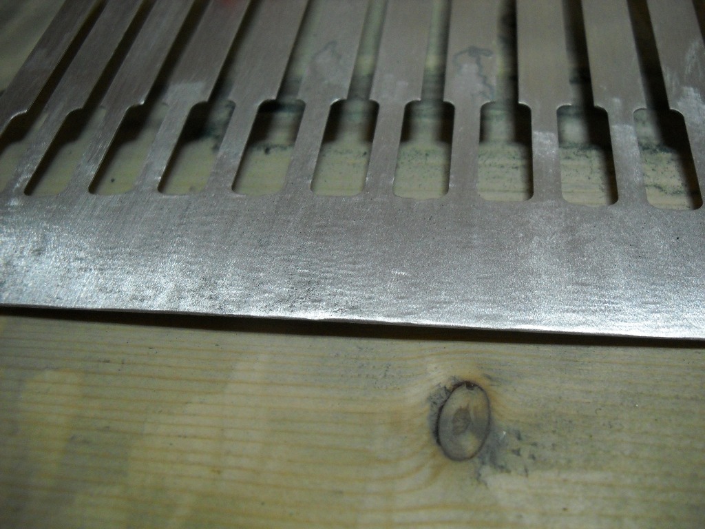
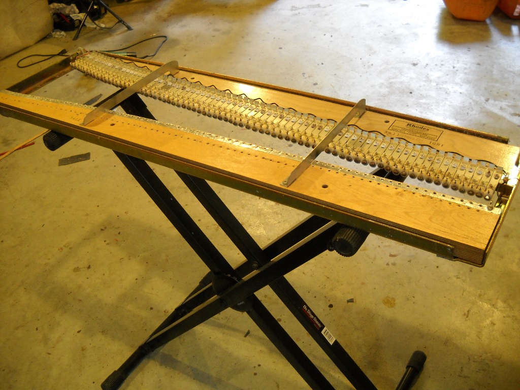
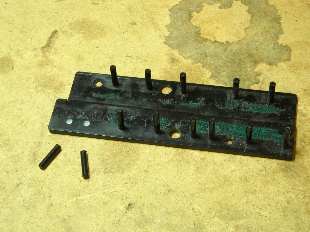
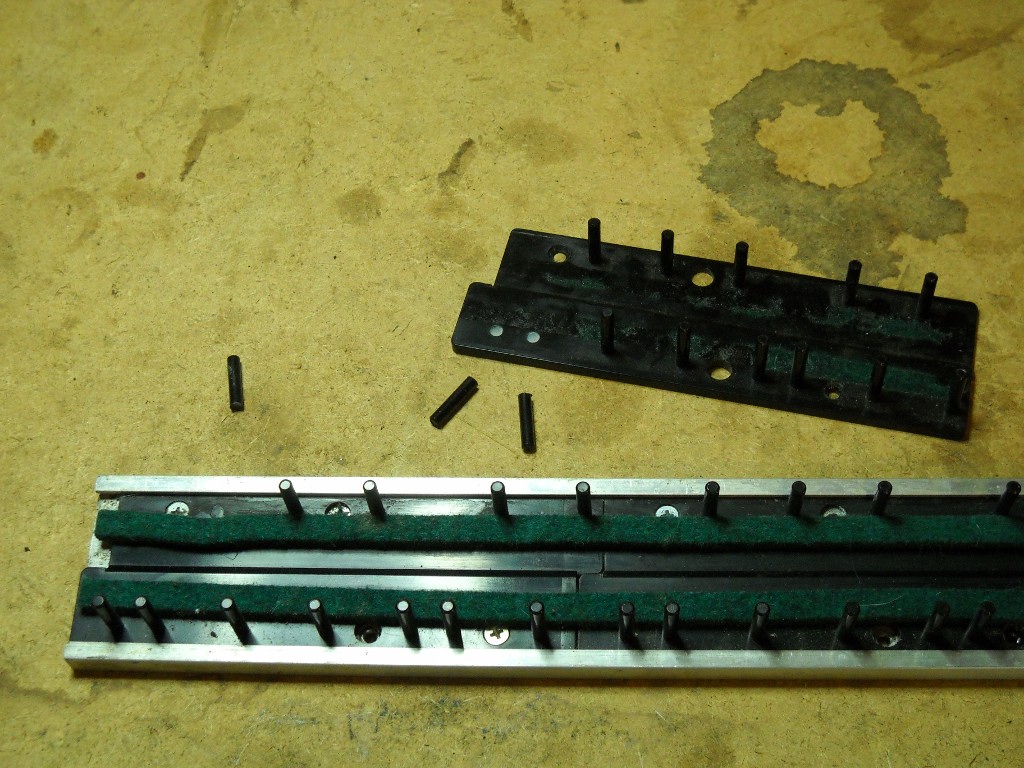
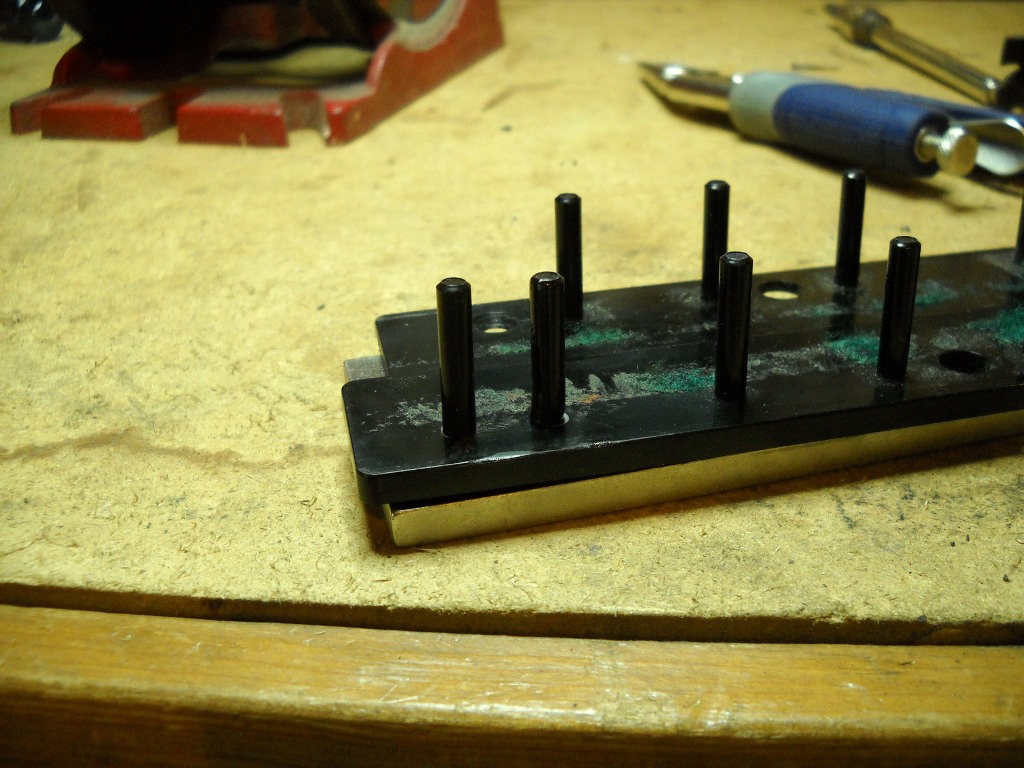
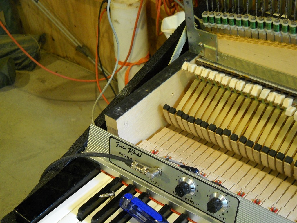
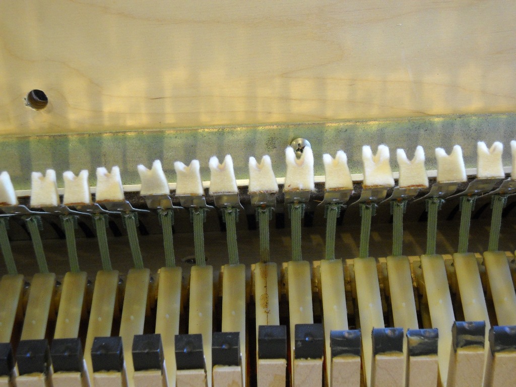
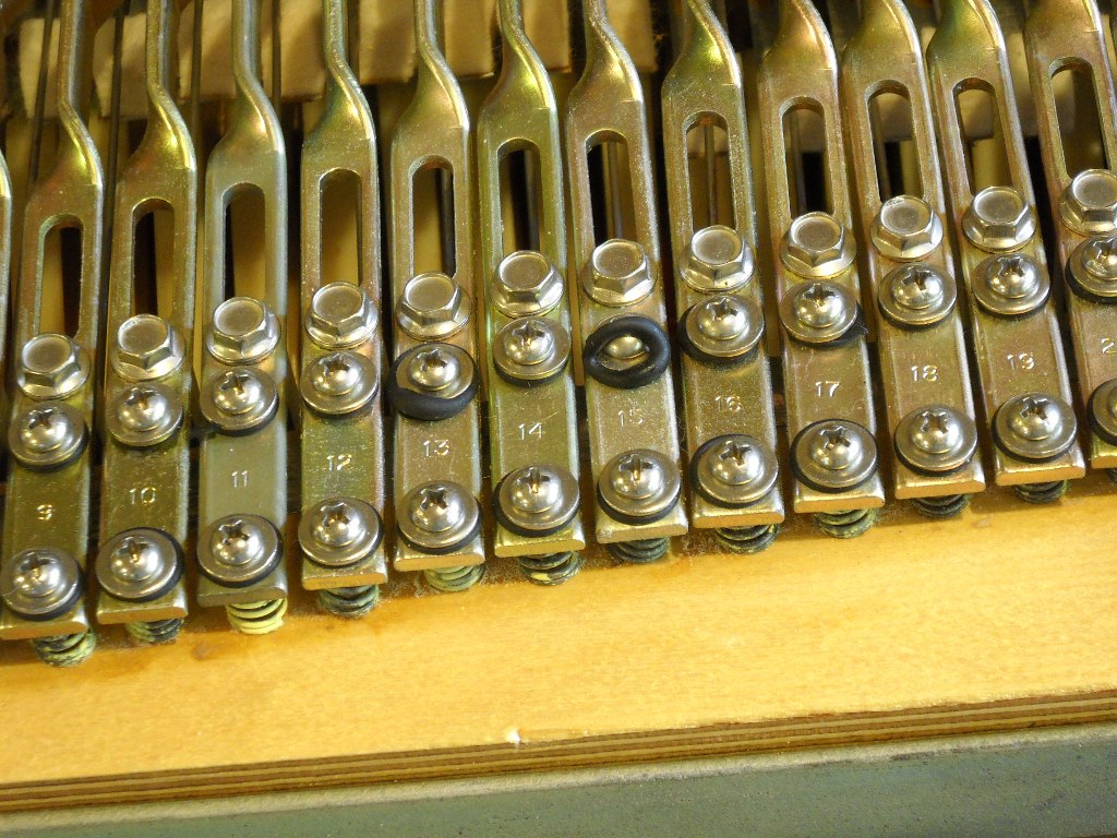
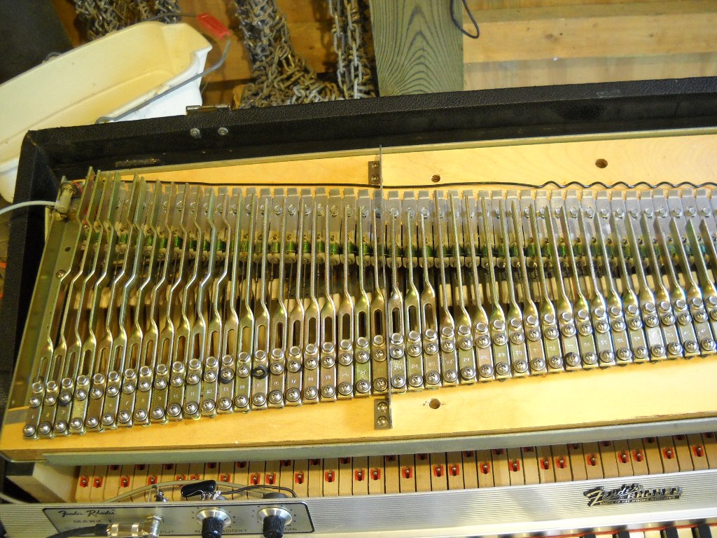
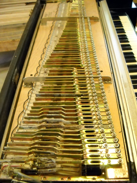
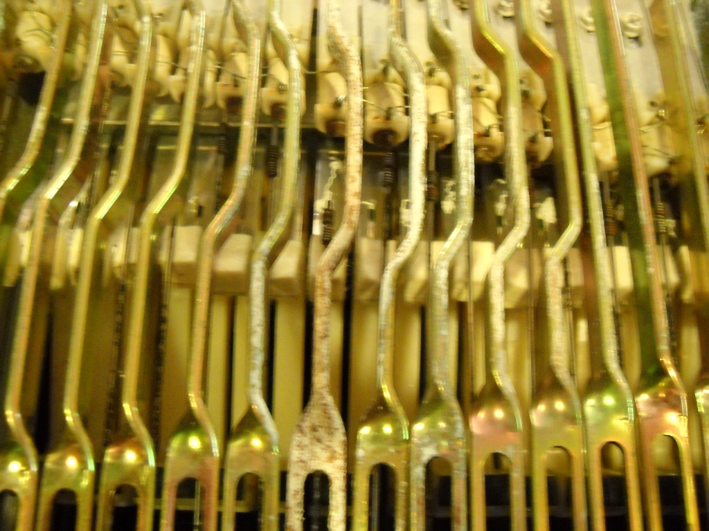
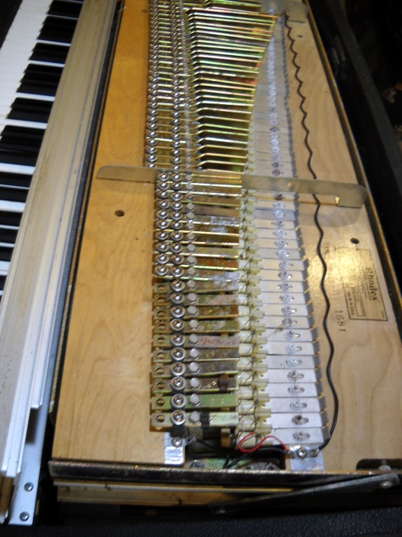
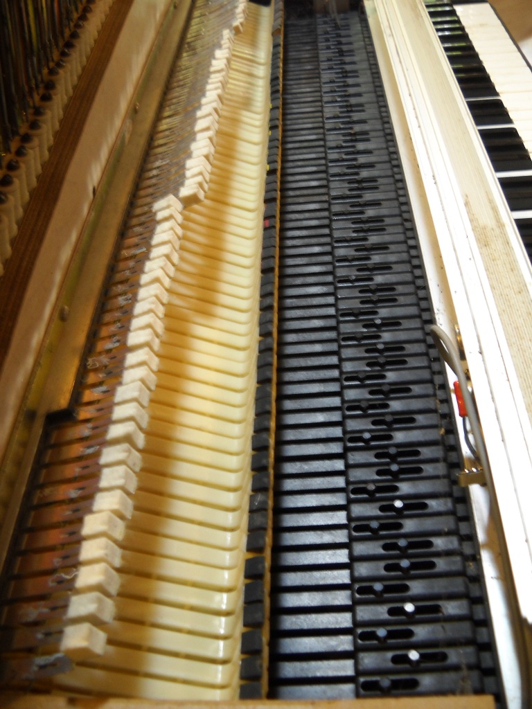
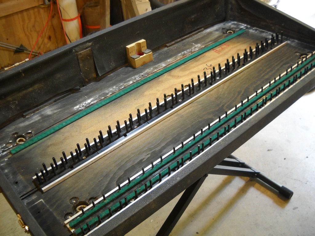
With their delicate, hair-thin copper wire, Rhodes pickups are particularly vulnerable to the dampness that only caused cosmetic damage to the rest of the piano’s components. After a pickup was wound at the factory, it was generally wrapped in plastic tape to protect the wire. Earlier pianos that I’ve seen were wrapped with clear tape while in later years, opaque white tape was used. The consensus seems to be that the pickups wrapped in white tape are more prone to broken internal connections rendering them completely dead. My guess is, it has nothing to do with the tape itself but probably the grade or type of wire used to wrap them. Even for a white-tape unit, this piano had more than its share of deads.

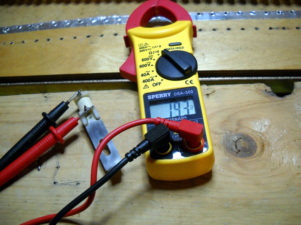
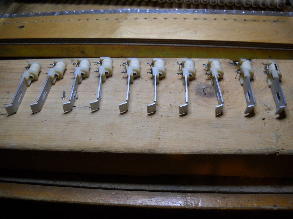
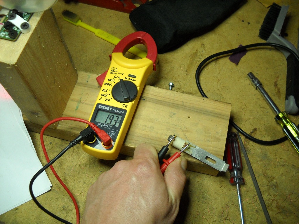
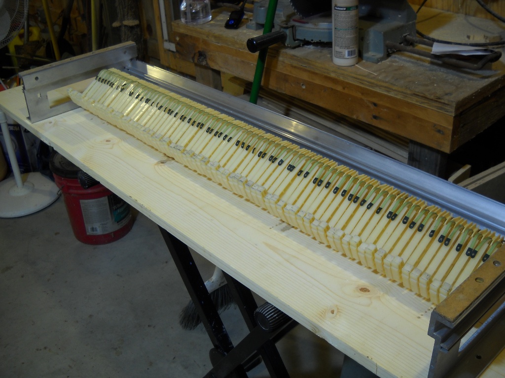
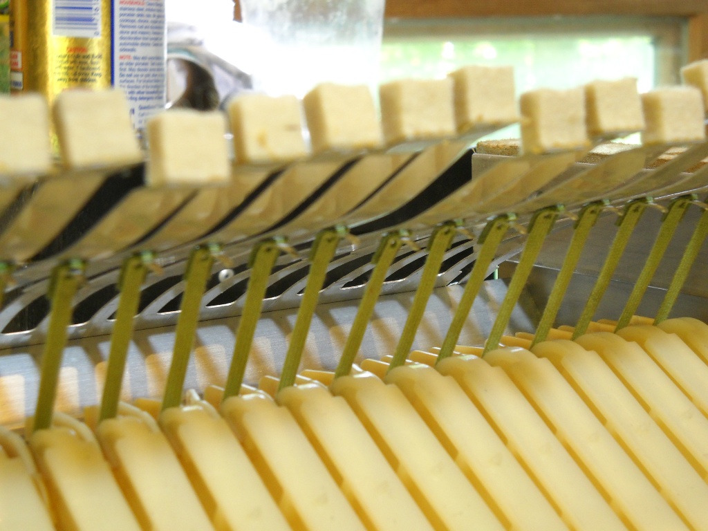
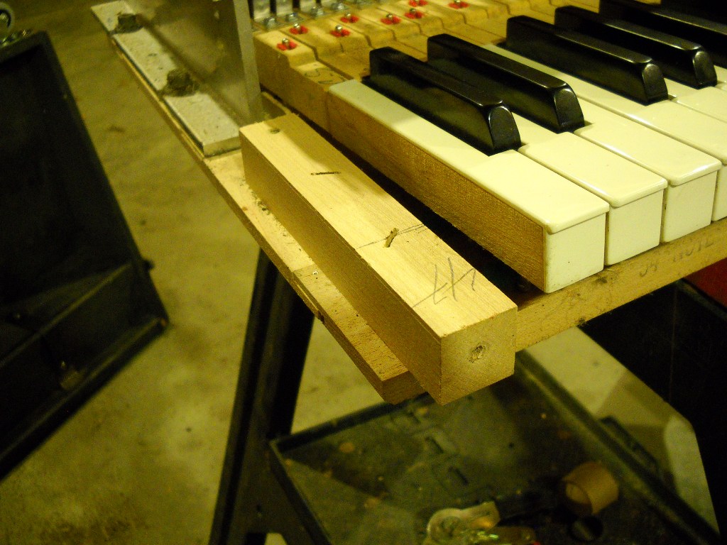
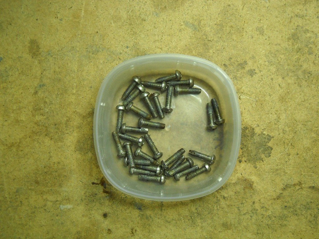
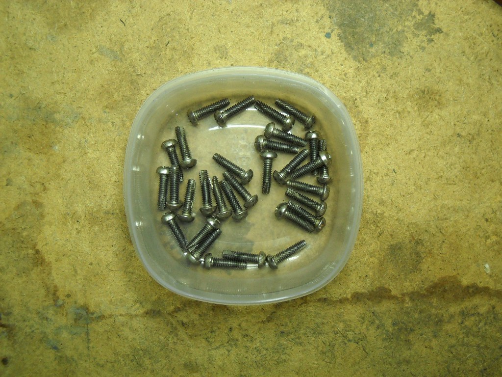
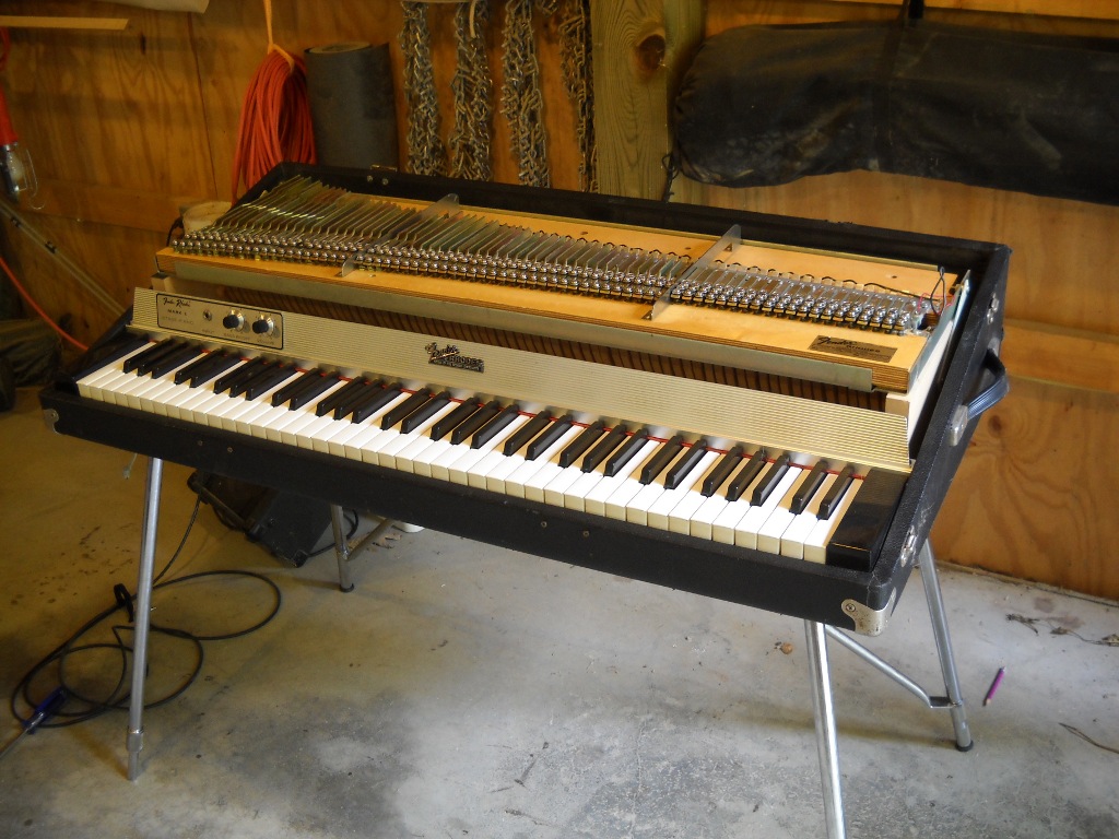
As pickups were removed, they were each tested. The good ones measured consistently in the low 190s which is right about where they should be. Others didn’t report any continuity at all and by the time I had removed the first twenty pickups, I knew by the size of the reject pile, I was going to have my work cut out for me. By the end, I had 46 working pickups and 27 out of commission.

I’ve wound Rhodes pickups before. My Fifty Four also features white-tape pickups and so far, six have expired on me. When I did those, I judged the amount of wire to use by measuring an original pickup’s diameter and comparing the new one. I have no idea how close I came to the correct number of wraps because it turns out that the 42 AWG wire I used was much thinner than the original and I ended up with a pickup that read over five times hotter than it should have. This time I was able to get some proper 38 gauge wire but I still wanted a better way to calculate the wrap count.

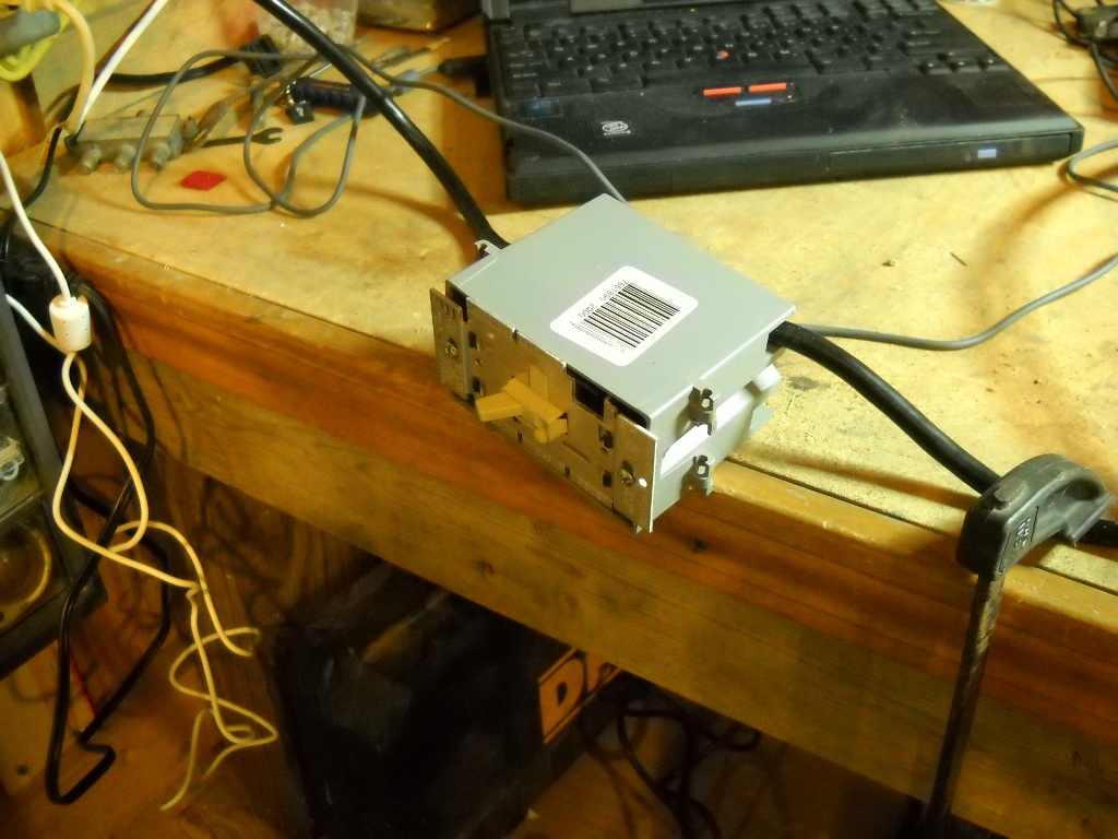
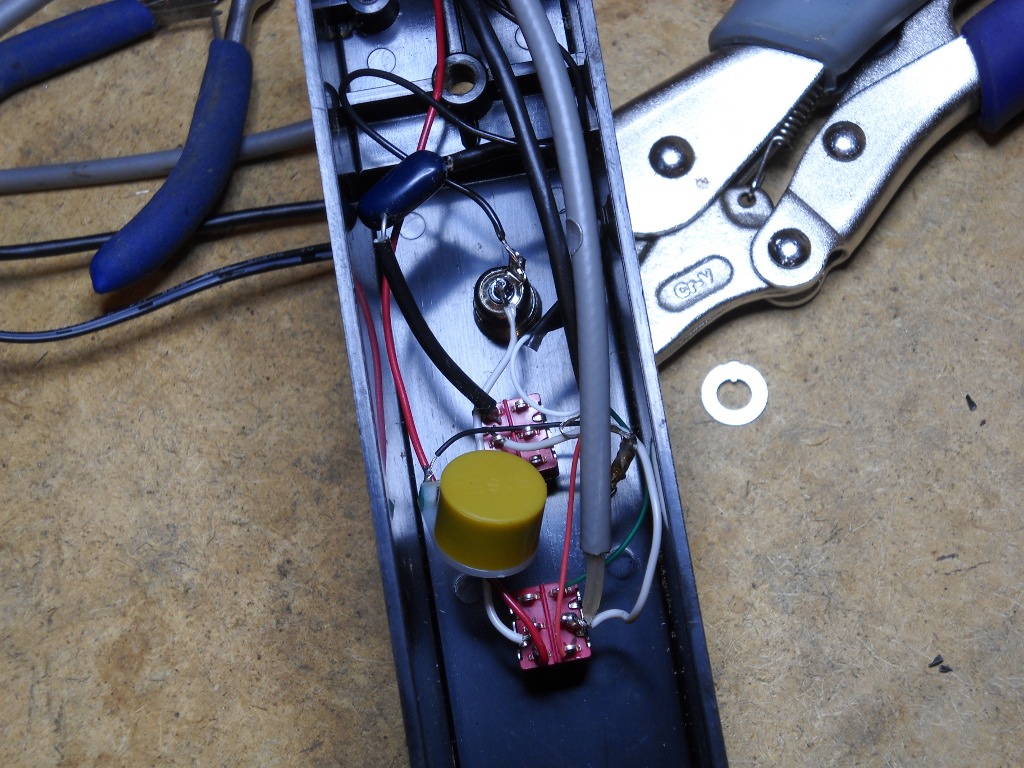
While looking for counting mechanisms on-line I saw some mention of using a computer mouse. The center scroll wheel on most mice uses an optical sensor to determine when the wheel has been moved. This can easily be re-purposed to count revolutions of a pickup winding spindle.

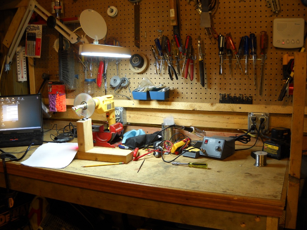
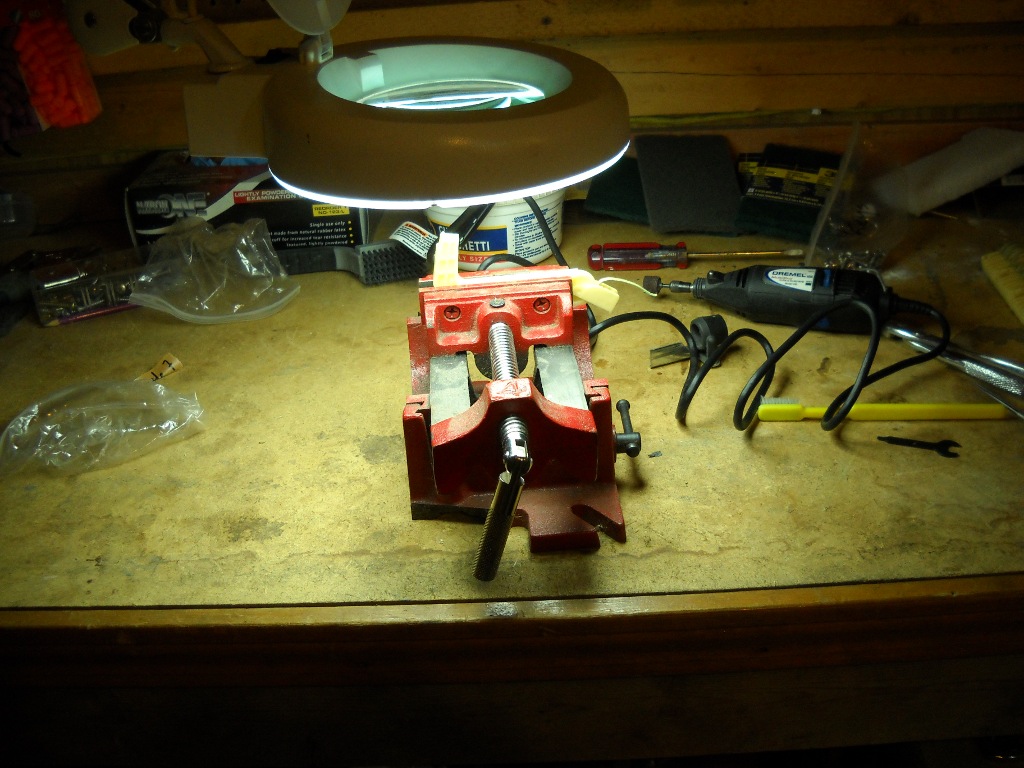
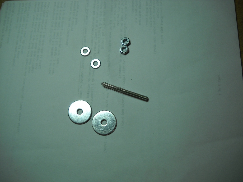
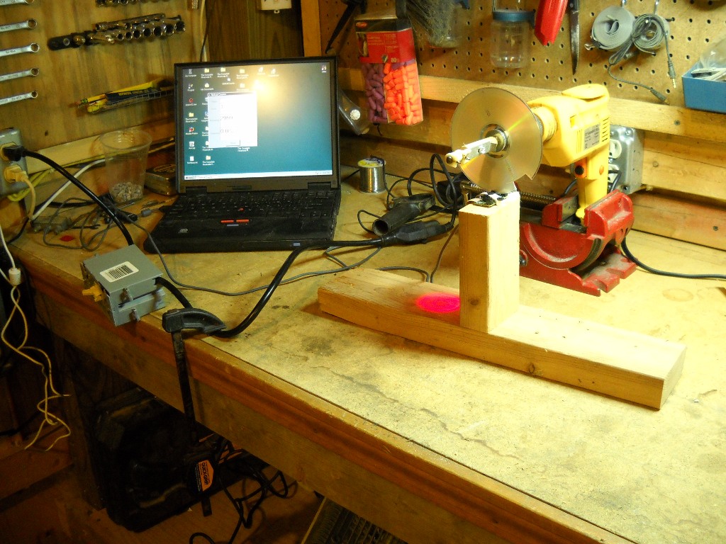
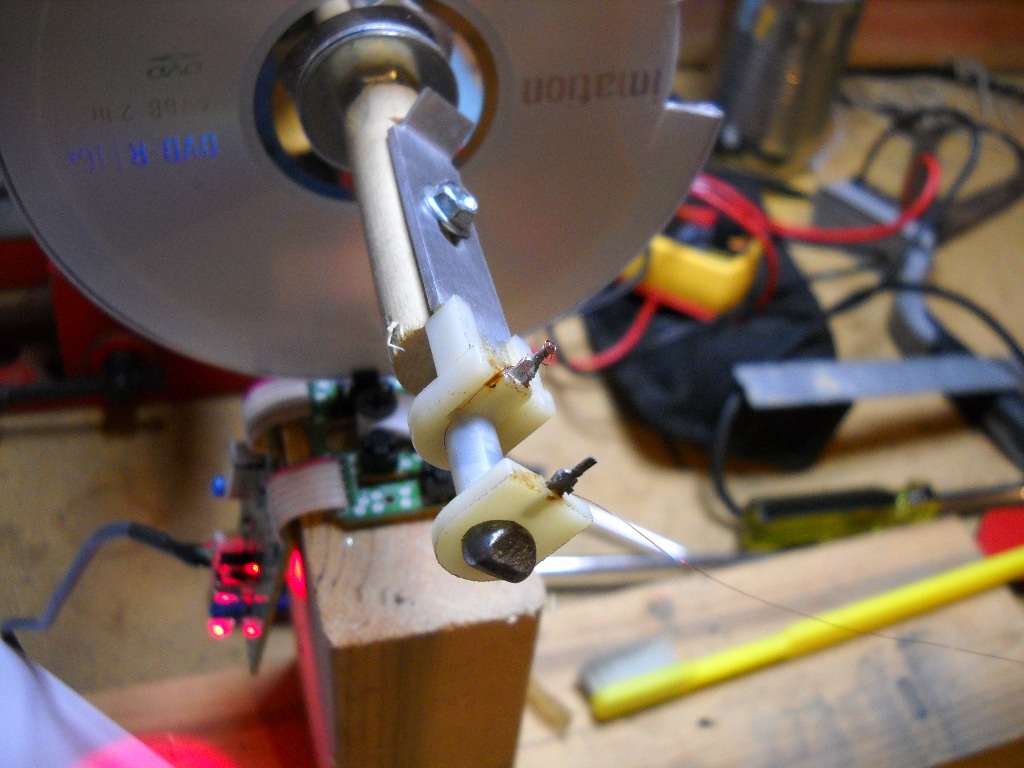
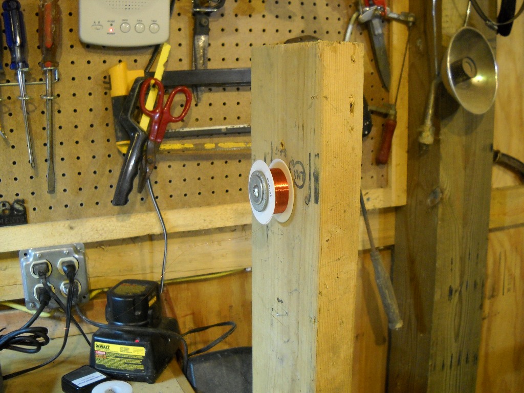
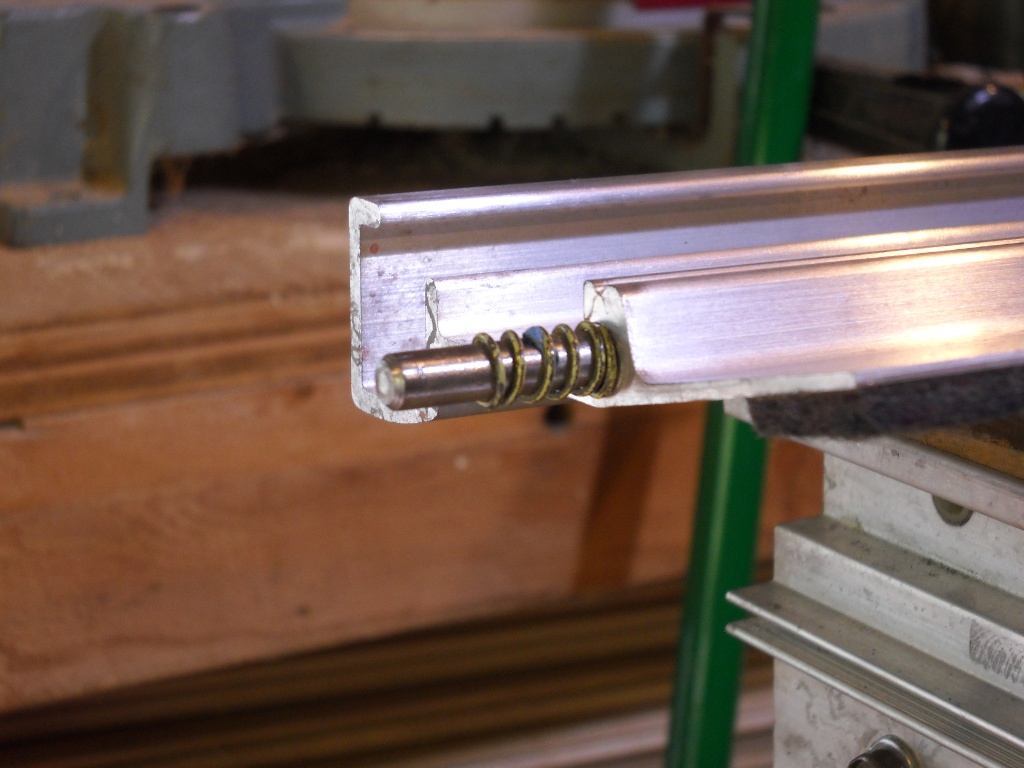
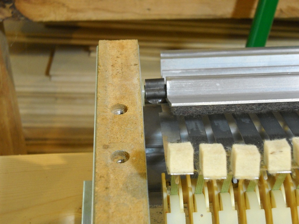
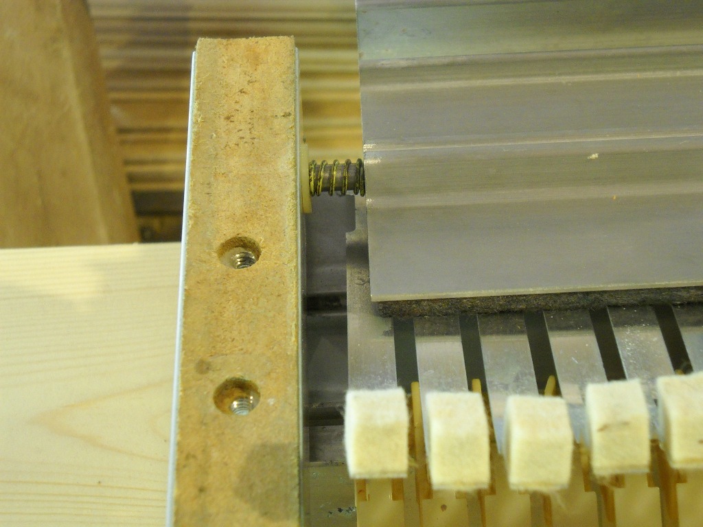
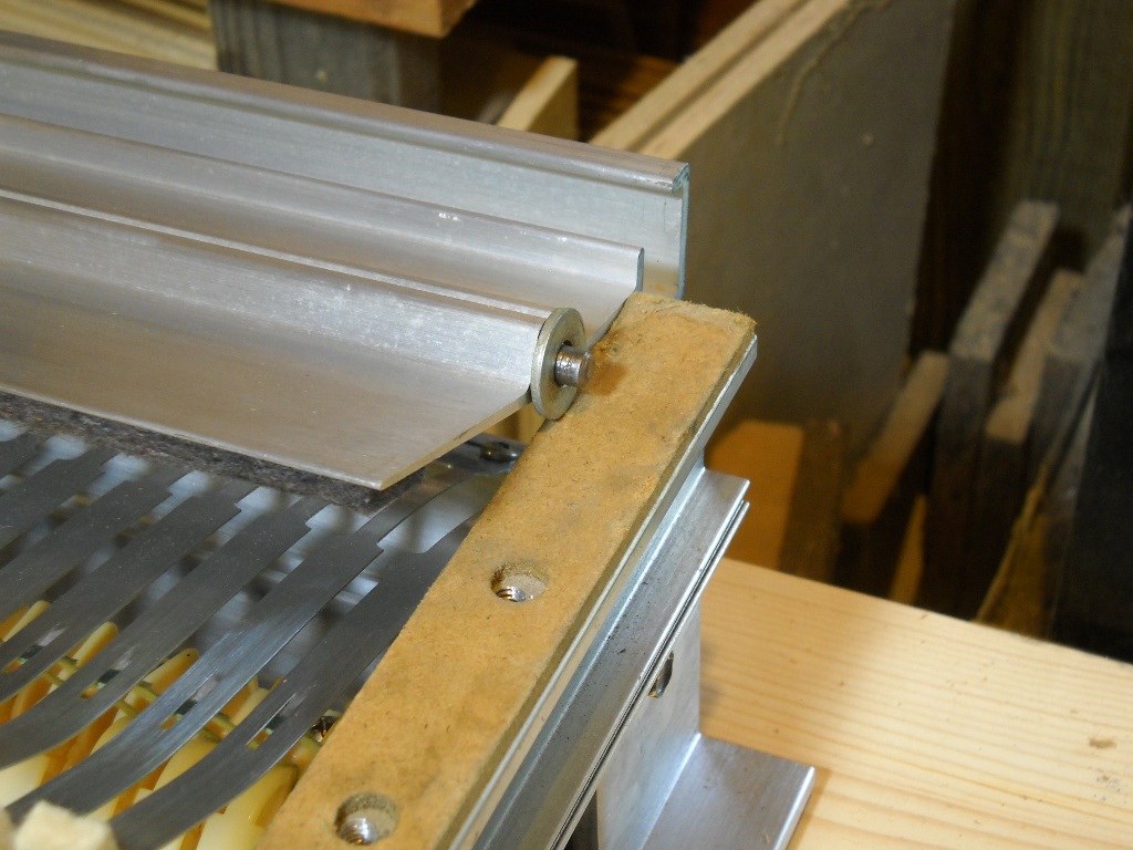
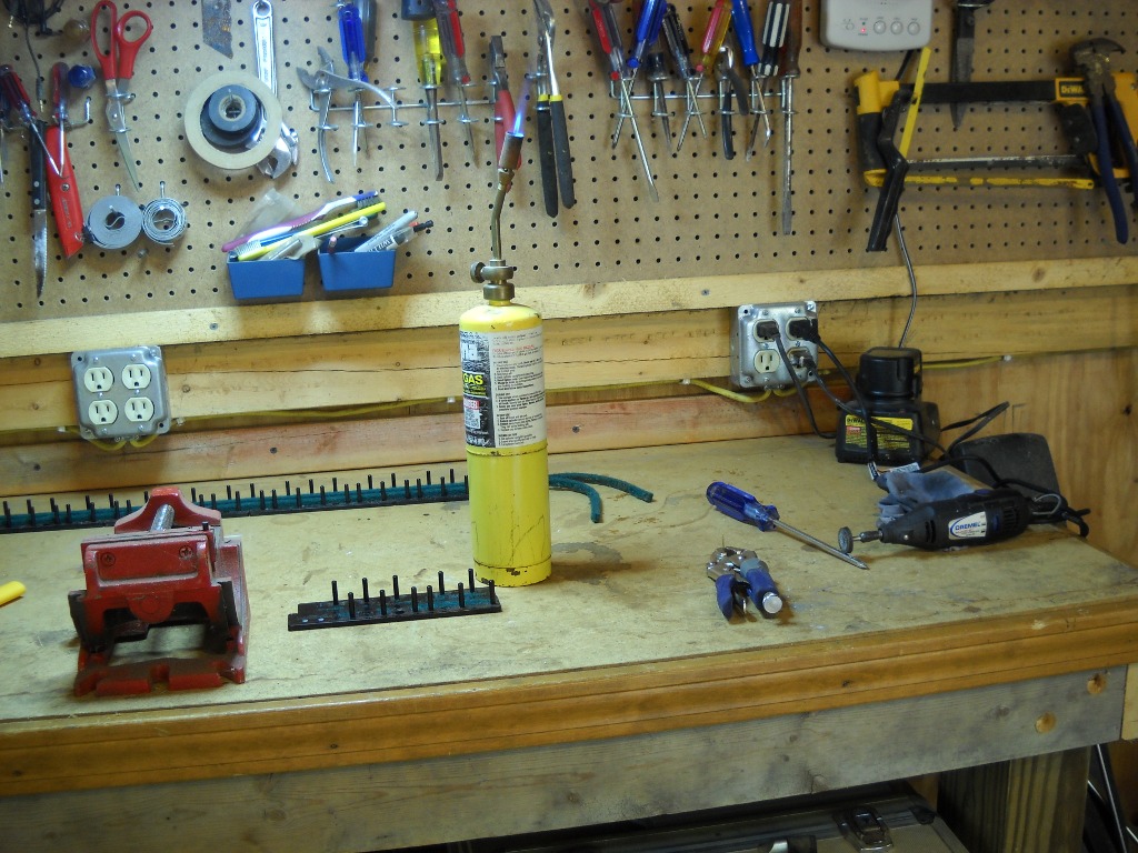
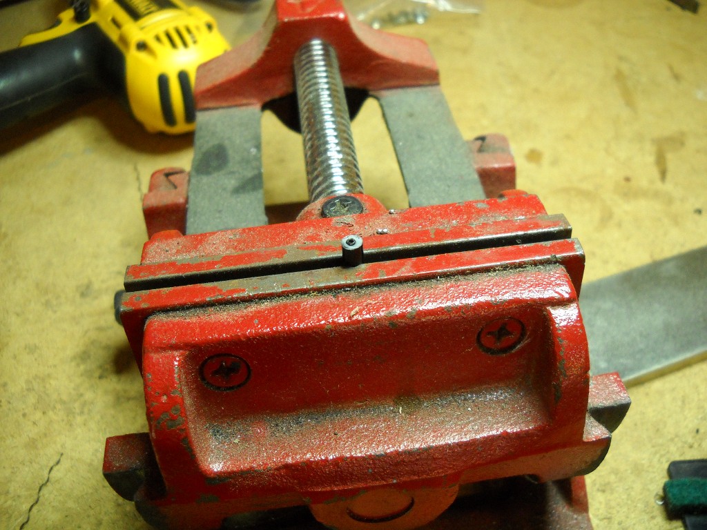
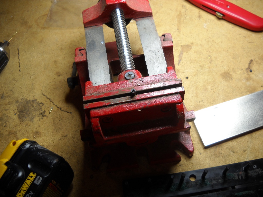
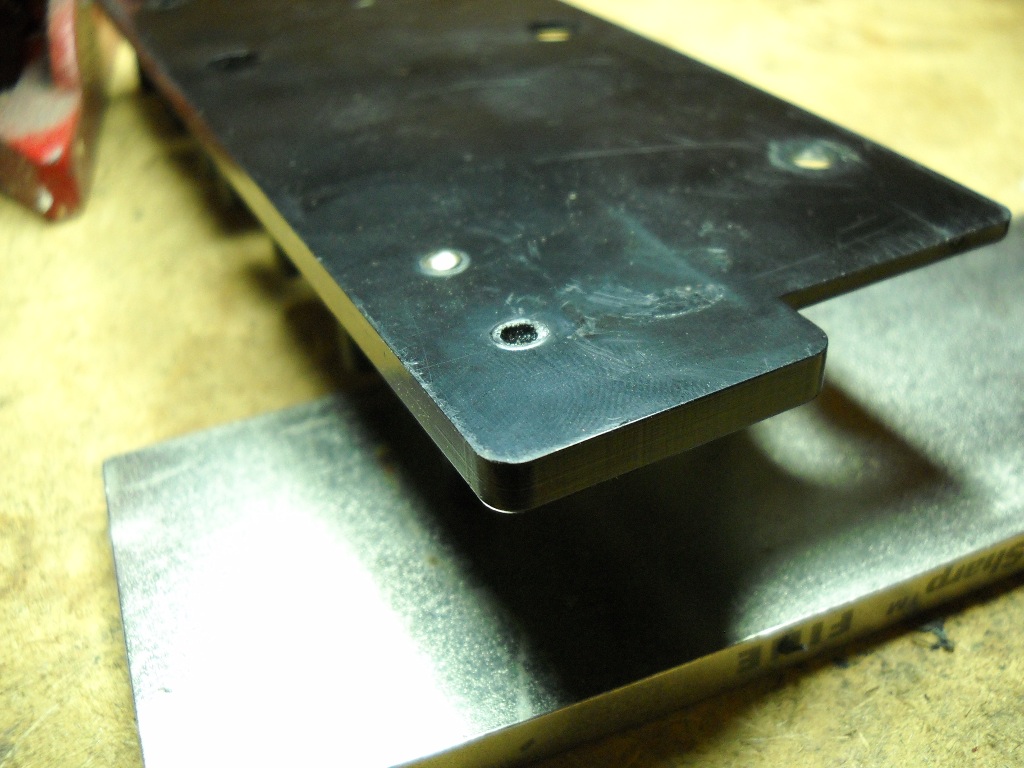
To replace the mouse wheel’s little pinwheel that serves to alert the optical sensor to movement, I went with a CD-ROM. I cut a small notch in the edge and mounted the disc to a hanger bolt with some washers and nuts. Next, a mounting block was made to hold the pickup as close to the center of the rotational axis as possible. The mounting block was screwed onto the wood-threaded end of the hanger bolt and the machine-threaded end was chucked into a hand drill which was clamped into a vise. The mouse sensor was just stuck to a two-by-four and the height of the drill was adjusted until the CD-ROM passed between its eyes. Now, for every rotation of the pickup, the sensor would see one brief glimpse of its sending unit and send a single movement signal to a computer.

To use the output of the mouse sensor, I wrote a small Visual Basic program. In addition to showing the number of rotations, a target can be specified and it will also show a count-down and a progress percentage (hmm.. maybe I’ll add a progress bar). An audible alarm would be very helpful so that I don’t have to take my eye off the pickup. I started to add a beep that increased in frequency as the target approached but ran into a little issue and set that aside.

The counter works amazingly well. I first tested it a few times by making around fifty to seventy wraps with string then manually auditing the count. When I started wrapping pickups, it took a few tries to arrive at a good number but it seems like 3,100 puts me in the best range. The first was a little low, the next a little high and the third was just right.

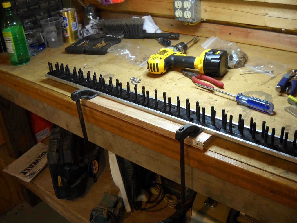
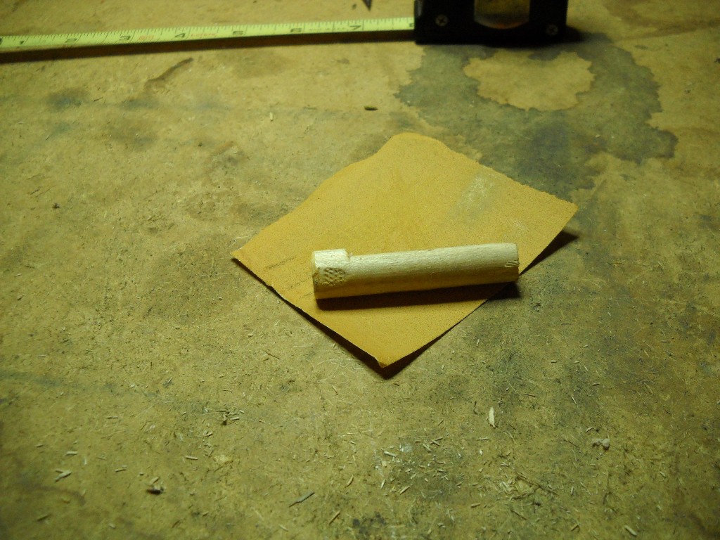
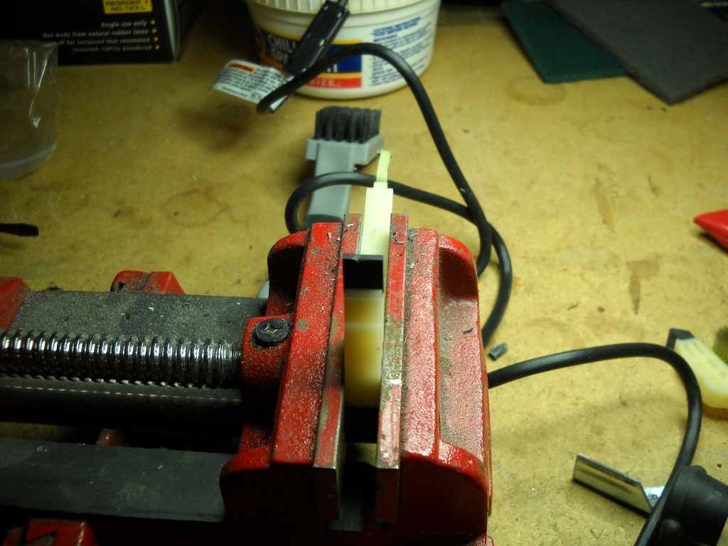
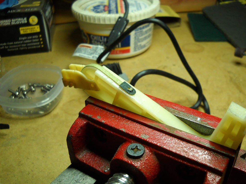
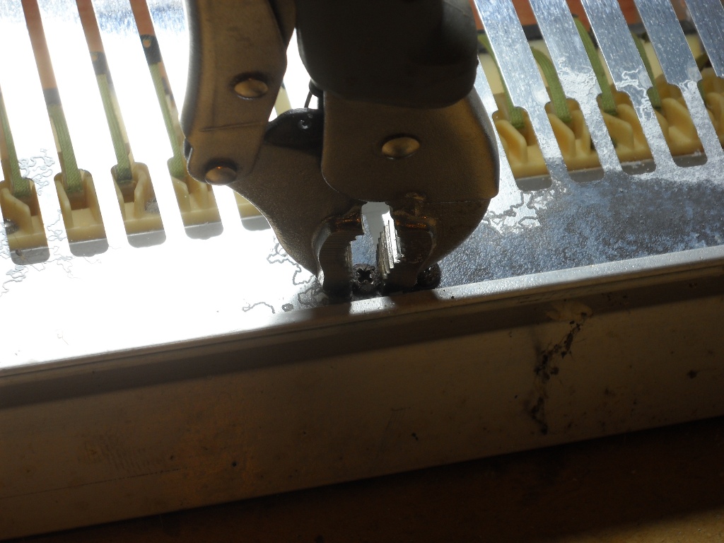
Before winding each pickup, the previous wraps were removed with a box knife. This actually turned out to be the most tedious part of the job. It was difficult to avoid damaging the plastic bobbin with the knife.

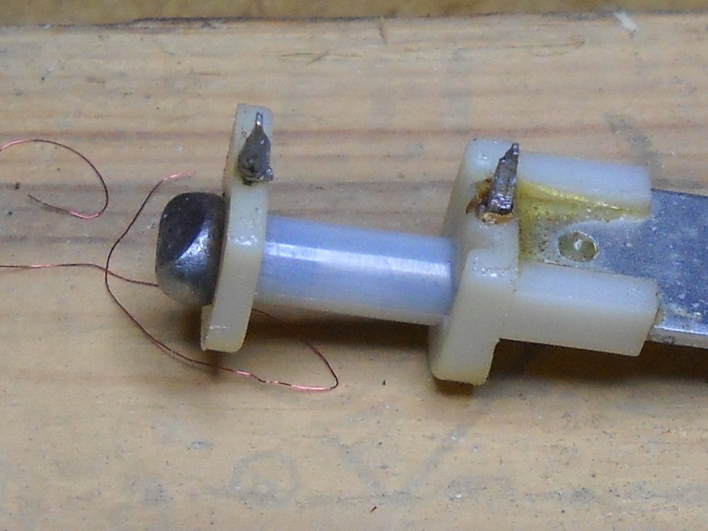
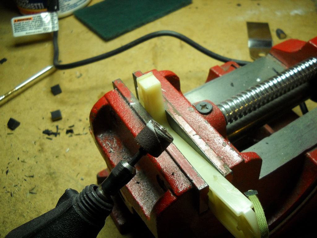
I don’t do much de-soldering and don’t have the proper tools for it. Besides that, I like to keep the number of times I heat up the lugs to a minimum as the plastic they’re mounted in tends to soften easily. So, instead of melting off the old solder, I used a small nipper to trim the lugs. This was important as any little snags can easily catch the wire as it’s being wrapped.

Even though pickup wire appears to be uninsulated, it actually is covered in any one of several types of coatings though I think generally either polyurethane or enamel is used. I believe I’ve heard that Rhodes pickups were wrapped with enamel-coated wire but I think my wire is poly. Either way, the insulation was first scraped off the end of the wire before it was wrapped around the lug to ensure good conductivity. The beginning of the wire is wrapped around the first lug – the one closest to the pickup’s mounting tab. Wrapping it clockwise around the lug helps the wire find the groove in the bobbin allowing it to reach the hub without obstructing the subsequent wraps. To wrap the wire around the bobbin in the correct direction, the drill was run in reverse.

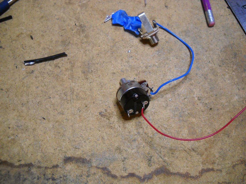
I wanted to be able to control the speed of the winder and using the drill’s trigger for this control was not a practical option. Since I also wanted to be able to start and stop it remotely, a dimmer switch was in order. I basically wired a dimmer switch into a short length of extension cord. This provided a pretty good range of speed control.

Note: this is not the proper method for controlling the speed of an electric motor. A common dimmer switch will eventually cause the drill motor to self-destruct.

I found that to get the correct number of wraps onto the bobbin, I had to make them pretty tight by pinching the wire between my fingers as it ran off the spool. The spool was mounted a few feet away, oriented so that the wire fell off the end rather than unreeling by spinning the spool. With this heavier wire it probably would have worked either way but lighter gauges may not be strong enough to handle the load of trying to turn the spool.

Using this setup, I’m able to wind a pickup from start to finish in about ten minutes. Again, the most time-consuming part is probably removing the old wire. Otherwise, it’s a pretty easy and fun job.

There are a couple of videos on YouTube. One of the counter being tested and another clip of an actual winding job.

The counter program can be downloaded here. It’s just an executable and doesn’t use any special libraries so it shouldn’t need an installer. Just download and run.

The source code for this program (much of which was copped from somewhere on the web) can be downloaded here. It’s written in Visual Basic 6.

Hammers and Dampers

I don’t think this piano was ever played much. The hammers showed only a little wear and all of the felt seemed to be in decent condition. I suppose it could have been serviced prior to being stored in whatever damp basement was its home for years but I think a disinterested owner is more likely. I’m going to stick with the existing felt everywhere except the bottom of the name rail but I replaced the hammer tips to give the piano the greatest chance of sounding and looking brand new when finished.

With the action completely disassembled from the piano, it was the most convenient time to work on the hammers. The first step was to remove the old tips. This was done by peeling the tips sideways until they broke free of the hammer end. The neoprene hammer tips on a Rhodes are grouped into five sets, each set is formulated to a different hardness. The softest material is used on the bass notes with the tips getting progressively harder as you move up the scale. The last and hardest set of tips have a wooden core to make them particularly hard. While the softer tips tended to leave remnants of rubber as they were pried off, by the time I reached the highest notes, the hard rubber was snapping off quite cleanly.

Even though the treble tips were breaking off cleanly, they still left an uneven surface of residual glue behind so every hammer was carefully cleaned using a small sanding drum on a Dremel tool. I first wore the coarse sanding drum down on some cast iron to take some of the bite out of it but it still required a steady hand to keep from cutting and burning the plastic hammer surface. As each hammer was cleaned, I snapped it back into the hammer comb already mounted to the action rail.

Since I was waiting on delivery of the new tips, I proceeded with the dampers first. The damper strips had some of the most tenacious corrosion I had yet found. I ended up resorting to the same Dremel sanding drum to remove most of the staining. The thin metal damper arms act as their own springs and as such are subject to metal fatigue over time and I’m worried that my aggressive cleaning tactics may have prematurely aged them. They’re relatively easy to replace so I’ll wait until the piano’s playable before deciding if they’ve still got enough spring in their step.

The dampers are connected individually to the hammers by way of a bridle strap so that as a hammer rises to strike the tine, its damper is simultaneously pulled out of the way. Old bridle straps can stretch out making it difficult to maintain the proper relationships between hammer, damper and tine. At first I wasn’t sure how to determine the condition of my bridle straps until I learned that the hammer comes equipped with a built-in length gauge. A small protrusion that I had previously thought was a remnant of the mold used to form the hammer turned out to be a hook placed there to aid the installation of the bridle straps. The distance from the hook to the strap’s anchor point marks the appropriate length for a correctly trimmed bridle. Since all of my existing bridle straps fit perfectly to that hook, I determined that they did not need to be replaced.

With the dampers all installed, I could finally reinstall the damper rail. Through the years, damper rail hinges have been designed in different ways. On this model, one of the rail’s hinge pins protrudes further out the side than the other. The excess length is occupied by a spare tone bar spring so that the opposite pin can be inserted while the spring is being compressed. The whole arrangement is locked into place by what appears to be an extra wide tone bar clip.

When I first installed the damper rail, I was concerned that it was only making partial contact with the lowest note’s damper spring. Since there was plenty of rail at the treble end, I decided to try to shift it a bit by the addition of a washer. The small shift was enough that it prevented the locking clip from being inserted so, rather than make any more modifications, I put it back the way it was.

By this time, the new hammer tips had arrived. These are installed by just gluing them in place with a small amount of medium viscosity super glue. When I replaced the tips on my Fifty Four, a couple of the high ones fell off after a little bit of playing. The hard rubber on the wood-core tips is very smooth and slippery so this time I first scuffed them with a small file before gluing them down.

With the action rail ready to go, I was able to reinstall everything and the project started to once again look like a real piano.

Tine Bomb Preamp

I’ve always been pretty happy with the tone of my Fifty Four. With the right voicing and through the right amp, it produced a sound that could hold its own amid other electrified instruments. That said, I’ve considered it to be lacking the range of harmonic content that could be heard from a full Suitcase model. Only on the very hardest of strikes are you ever rewarded with a hint of the crunch that gives other models so much character. Vintage Vibe’s new Tine Bomb Preamp is designed to help make up for the shortcomings of the Stage’s passive electronics by fattening up the sound both in breadth and strength.

The Tine Bomb arrives with everything needed to retrofit a standard Stage Seventy Three with no soldering and nothing more than a screwdriver and a drill with a 1/8″ bit for tools. The supplied RCA patch cable, tone and volume pots and 1/4″ jack are drop-in replacements for the existing electronics. The new volume pot is also the power switch for the preamp. Unfortunately the new components are not matches for a Fifty Four which features fader-style tone and volume controls.

The preamp is powered by a 24 volt DC wall-wart transformer. A barrel-style power jack comes mounted in a replacement cheek block. I debated for a while whether to use the supplied cheek block or remount the jack in the original block. At my day job, I’m frequently reminded of the value of original components once an instrument moves from being old to being collectible and I believe Rhodes pianos are already beginning to make that transition. The new cheek block was exactly the same dimensions as those from both the Fifty Four and my 80’s Seventy Three although the plastic-keyed Seventy Three fastens its cheek blocks with a tab rather than a screw in front. The replacement block was not as dimensionally consistent though and the sides cupped inward a little bit. Once installed, this probably wouldn’t be noticeable. Although not for that reason, in the end I decided to re-use my original block.

Since I was going to have to do some rewiring anyway, I decided to add a few more options to the setup at the same time. The main feature I was interested in was the ability to bypass the preamp but I also wanted to be able to select through which tone control the sound would pass. The Tine Bomb is pre-wired using a choke rather than a capacitor for the tone circuit. I’m not familiar with the effect produced by a choke and I was concerned it may not work as intended when bypassing the preamp. To put all of this together required the assistance of two double-pole, double-throw mini toggle switches (actually, the tone selector only needed to be single-pole) and a little shielded four-conductor wire. The project also gave me my first chance to try out my new soldering rig.

I first drew up some fairly crude wiring diagrams to both figure out the workings of the old controls and also plan the integration of the preamp. The switches and power jack were wired and installed first. The power leads connecting the cheek block jack with the preamp include a connector plug allowing the two to be easily separated. This allows the nameboard to be removed from the block without having to cut any wires. Unfortunately, I didn’t consider this convenience when drawing up my plans and will have to come back later and upgrade the installation.

Update: I feel I should note that the wiring diagram in the picture linked in the post is not complete or correct. I didn’t expect it to actually be legible in the photo. It doesn’t include the tone control switch and it’s missing a ground connection on the volume control.

I also didn’t plan for the block of wood used to mount the cheek block to the key frame. The wood obstructs most of the space inside the hollow cheek block and makes wire routing tricky. Luckily just enough room remained to accommodate the electronics and with a little finagling, I was able to keep the wires from being crushed on their way out the back.

The preamp itself mounts to the nameboard by a single screw through its heat sink into an 1/8″ hole in the base of the rail. If the hole in the rail is drilled at the proper location, the edge of the preamp’s circuit board butts against the rail keeping things from pivoting on the single screw. I didn’t really pay attention to the instructions when I chose a location for the hole in the rail. Although I positioned it as close to the output jack as I could, it still only barely avoids being hit by the harp frame. Had I read the instructions, I may have realized I was supposed to orient the preamp vertically rather than horizontally. It seems fine as it is but I may change it when I add disconnects to the new wiring.

Though my karma account probably took a huge hit for it, I was happy to find everything working properly when I finally plugged it in. The new sound was definitely fuller but it was mostly LOUD. My little Kustom KLA-10 practice amp was not able to handle the signal cleanly unless it was reigned in significantly at the piano’s controls. My Fender Stage 160 seemed much more tolerant of the hot signal and produced a clean but ear-bleedingly loud sound even at the lowest volume settings.

The difference between using the capacitor and the choke for tone control is significant. The choke is supplied as a “bass cut” to help bring the sound out of the mud if necessary. I found it useful as a way to tame the signal without having to drop the volume so much.

I’m not a tone connoisseur and don’t have much to say about the new harmonic content provided by the preamp. Even if I had a more discerning ear, a fair assessment would not be possible running through a Kustom KLA-10.  Although it still does not sound like an all-wood early seventies Suitcase model, I am able to get a noticeable amount of expression from the keys that was either difficult or impossible with the passive electronics.

I recorded a short video to demonstrate the preamp’s effect. The sound was recorded using the camera’s built-in microphone so the video does less to demonstrate the tonal qualities as it does the differences in output levels. The video focuses on the controls of the piano. On the cheek block, the first switch controls both the DC power and also whether to send the signal through the preamp (Up) or around it (Down). The middle switch selects between the original capacitor (Down) and the choke (Up) for tone control.

  • Update 9/5/11

I added a couple of .wav files to try to demonstrate the tonal effects of the preamp. I attempted to play the same piece of Recorda-Me, once with no preamp and again with the Tine Bomb turned on.

  • Update 10/1/11

In a discussion on the Electric Piano Forum, Chris Carroll of Vintage Vibe advises that when ordering a Tine Bomb, you can specify that it will be installed in a Fifty Four and they will make the necessary adjustments so that it can handle the increased signal strength.

Action Rail

The action rail is an aluminum bar that supports both the hammers and the dampers. It in turn is supported on each end by the harp supports and the whole assembly is bolted to the bottom half of the plywood case. After removing the harp frame, the action rail was completely disassembled. One end of the rail was much more corroded than the other and a few screws needed some convincing before they’d come out.

Most of the action rail was covered in corrosion and some white dust. When I cleaned the guide pin rails, I used Barkeeper’s Friend with decent success. I started cleaning the action rail with Barkeeper’s Friend and a Scotch-Brite pad but it was messy and I soon learned that a dry Scotch-Brite pad by itself was the way to go.

As I disassemble the piano, every screw that appears salvageable has been cleaned up on the bench grinder’s wire wheel. Although it probably also strips plating, the wire wheel is very effective at removing all rust and corrosion from the screws.

The cleaned action rail still shows some pitting where the worst of the corrosion was but, all in all, its condition has greatly improved.

Key Guide Pins

I knew when I first saw them that the key guide pins were fragile. Obviously, they would require careful handling and storage while they were outside the case. It was with this in mind that I began cleaning their aluminum rail and promptly broke two pins. And then I broke one more.

I don’t know where I can get replacements for these. There’s a seller on ebay that has the balance rail pins but not the front guide pins that I’d broken. My only option was to attempt a repair. When an unorthodox repair procedure is called for, one of the first tools I usually reach for is a torch and this job was no exception.

I heated up a picture hanger nail and used it to poke a hole in the plastic base. I also used the hot nail to kind of center-punch the underside of the pin. A drill bit was used to finish the hole in the pin.

My plan was to drive the picture hanger nail up through the base to support the plastic pin. The nail head protruding from the underside would prevent the pin base from sliding into the aluminum channel so I melted a little divot to allow the nail to sit flush.

The hole I’d drilled in the pin was slightly smaller than the diameter of the picture hanger nail. After pushing the nail through the base, I carefully heated its tip and pushed the pin down over it. The plastic melted just enough to provide a surprisingly snug fit. The repaired pins were sturdy and ready for action.

Rhodes Caddy

When I started lugging my 54 around to shows, I soon decided that it needed casters. When I restore the case on that piano, I won’t want to ruin the original look by reinstalling those casters. Also, with a small shop, I need to be able to move other pianos around easily. Building a dolly out of angle iron was a very easy, straightforward project.
Materials included two five-foot pieces of angle iron, four 2″ casters, 16 1/4″x1 carriage bolts and 16 1/4″ nylon lock nuts. After cutting the angle iron, the unit just bolted together. At first, I planned on installing cross bracing, but after tightening the corners, it was clear this was unnecessary. The 1″ carriage bolts were the smallest I found but they were still too long and obstructed the motion of the caster so I cut them off after tightening everything down.
Some strips of 1-1/4″ foam rubber weather stripping added the finishing touch and made for a (nearly) perfect fit.

1973 Seventy Three Mk I

When referring to these pianos, most people say “Fender Rhodes” even though the Fender name only appeared on units for 9 of the 22 years they were in production. According to the Fender Rhodes Supersite, there were no changes to the piano’s construction that coincided with the dropping of the Fender name. So for all practical purposes, there is no difference between a Rhodes and a Fender Rhodes. Regardless, I wanted one with badges that included “Fender”.

Once again, eBay came through for me and I paid what was probably too much for a 1973 Seventy Three Mk I. The seller had acquired it at an auction at a university where it had been in storage for many years. Like the last eBay purchase, this one included all components. This time, it even included the legs and sustain pedal. The only things missing are a few pieces of case hardware, the knob for the leg braces and the vinyl leg bag.

In 1973, Rhodes were built with wooden harp supports instead of aluminum. The hammers were “hybrid”, made up of both plastic and wood. What I don’t know is whether the damper felts are extremely misshapen or were designed to partly wrap around the tine like on an acoustic piano. The pickups on this one were wrapped with a cool green wire. I’ve had to re-wrap six pickups on my 54 so I was surprised to find that this one, like the last 73, seemed to have all of its pickups intact.

The case and Tolex have a few road scars and had been outfitted with some aftermarket latches. I don’t even know how double-hung window locks could have held the case closed. A few tone bar grommets have blown out and some hammer tips are missing but other than that, the interior is in pristine condition.

Tolex

Using one of the old pieces of Tolex as a template, I began by cutting the sides from the new material. I decided against trying to use any of the old face pieces as templates as they were too torn and brittle to work with.

I worked on the bottom half first. With no leg compartment and only one face surface to take care of, it would be a simpler job to start out on. I thought it might be easier to spread the glue with the case hanging from a roof truss. This turned out not to be the case and when I got to the top half, I didn’t bother with that apparatus.

I applied the Tolex glue liberally to both the case and the fabric using a small 4″ paint roller and a foam brush. After waiting about 15 minutes for the glue to become tacky, I applied the first end piece. Although it went on well enough, I was a little concerned that the glue wasn’t holding as well as it should. The glue is touted as having an extraordinarily long working time (like days or even a week) but as the job progressed to the face piece, its poor short-term performance was making things a little frustrating.

I found the screen repair tool I had to be very useful in creating tight inside edges.

I spent a while trying to smooth the flat surfaces and keep the edges tight but eventually decided it was an act of futility and left it for the night. By the next morning things were looking up. The glue had finally agreed to display its adhesive characteristics and I was able to touch up a few trouble spots from the night before. As further time passes, the glue seems to be improving its bonding strength and I’m more confident now that it will mature to an appropriately semi-permanent finished product.

All in all, I’m pretty happy with the way things turned out. There were a few victories and a couple of lessons learned. I started with four yards of Tolex and had only barely enough to cover all surfaces.

Case Preparation


After removing all of the external case hardware and everything from the inside, it was time to peel the Tolex. In some places, the glue was still holding strong and the vinyl took some wood with it. Other areas had clearly seen more moisture and gave up their covering without a fight.

The Tolex repair video produced by Vintage Vibe says to use the old pieces as templates for cutting the new ones. Some pieces were better suited than others for this. Luckily the more intricate end pieces survived largely intact.

Eventually, both halves of the case were freed from all remnants of Tolex. About three hours and a couple of 80 grit sanding discs later, they were taken down to bare wood. Removing the old glue from inside the leg box was exceptionally tedious and eventually I had to quit and call it good enough.

Despite having gotten wet, the plywood seems entirely structurally sound. The only places that were a little soft was where screws had transmitted moisture into the wood. Several of the old screw holes needed to be drilled out and plugged with new wood. I ended up deciding to just refill all of the spots where wood screws would need to grab hold.

Before putting on the new Tolex, all of the nicks and dents needed to be filled with Bondo. Finally, after another pass with the orbital sander, the case was ready to be covered.