Open for business

After restoring my own pianos for four years, I’ve decided to open my shop to customers’ instruments. Each of the six pianos I’ve restored to date were stripped down entirely to their individual components and rebuilt. So I feel confident in taking in others’ instruments – confident that I know how to perform typical repair and maintenance procedures and that I can do the job correctly with the initial learning curve behind me.

For a couple of years, I’ve been posting my financial and labor records on this website using my ShopChart management application and I plan to continue doing so. Between ShopChart and the photos I post to this website, customers will be able to keep close track of the progress of their instruments.

I’ll offer full restorations, individual repairs or even service on individual components like keys and pickups. And although I don’t work on electronics, local amplifier repairman and former Rhodes service technician Paul Schmittauer has agreed to handle work on the amplifiers and preamps of any Suitcase pianos that might come my way.

Miracle Mod

Of all the components that make up the action of a Rhodes, perhaps none is more important to the feel of the keyboard than the key pedestal and hammer cam. The interaction of these two parts is responsible for causing the hammer to strike its tine, preventing the hammer from bouncing on its return and limiting the downward motion of the key. Several different designs of both pedestals and cams were used at different periods in the production of Rhodes pianos. Of the various pedestal designs, it is generally agreed that those which display a flat profile or one that falls away in the front produce an undesirable playing feel. Pianos with such a design tend to feel both heavy and mushy providing no distinct sense for when the hammer is flung upward or when it returns to its stop-lock position. Unfortunately, flat-top pedestals were installed at the factory for much the first half of the 70’s.

Luckily, the cure for poorly-designed pedestals is a simple and inexpensive one. Commonly called the Miracle Mod, its effect on the action is such that the name is not considered hyperbole by most. Opinions vary on the exact implementation of the modification. Generally speaking, it involves the addition of a small bump to the front of the key pedestal. The shape and location of the bump though are matters of some dispute among practitioners. For the four installations I’ve done, the half-round bumps supplied by Vintage Vibe were used and my placement was guided by their YouTube video on the subject as well as information from the Electric Piano Forum.

The Vintage Vibe video linked above would lead one to believe this job can be done without having to remove the pedestal felts. The piano they used was built around 1976 during a period when Rhodes installed the felt onto the hammer cam rather than the key pedestal. With a piano of that vintage, the bump can indeed be installed onto the pedestal and the felt left on the cam but I wouldn’t expect such an arrangement to hold up for very long. Even using a glue formulated specifically for the job, it’s difficult to reliably adhere such a small piece of plastic to a wood surface. Installing the felt on top of the bump helps a great deal in securing everything in place. Since there isn’t room for two pieces of felt between each hammer and pedestal, the material glued to the hammer cams must be removed. When I removed the felt from the hammers of two pianos from 1976, I found naphtha made the job fairly easy. With only a little effort, I was able to remove every trace of the felt’s adhesive without damaging the plastic hammer. I struggled to remove the felt from the pedestals of the 1973 I’d worked on previously. After trying several less aggressive methods to loosen the glue, I finally settled on acetone. The felt’s glue responds very well to acetone but this is also true of the plastic key tops which are instantly disfigured from contact.

Changing the shape of the pedestal with this modification affects the action in two ways. At rest, the hammer cam sits atop the small bump, reducing the contact patch and thus the amount of friction between the cam and the pedestal and changing the leverage involved in causing the hammer to move upward. After the tine strike, the bump helps enforce the action’s stop-lock mechanism by adding a second point of contact to more effectively catch the hammer on its rebound. It is this stop-lock position that I use to find the appropriate location for the bump. To make the job easier on my current 1974 piano, I first removed the harp supports giving me a clear view of the hammer and pedestal. With the first key held down and the hammer at stop-lock, I placed a plastic bump on the front of the pedestal and pushed it back until it made contact with the hammer’s cam. I then marked the side of the pedestal with a pencil and removed the key from the frame to strike a guideline across the face of the pedestal. Of the two sets of components, the hammers maintain a more consistent line across the length of the piano than the key pedestals. Installing the plastic bumps by measuring a set distance from the edge of the pedestal will likely result in a more irregular response than if the measurement was made relative to the action rail. In order to draw a reference line across the entire set of keys that would remain parallel to the action rail, I located the proper position of a second bump at the opposite end of the keyboard from the first. Then  the action rail was removed and with it the hammers and dampers that blocked access to the rest of the key pedestals. With what in my shop passes for a straightedge clamped down at the marks made on the first and last keys I drew the lines across the remaining pedestals.

Since the felt to be glued on top of the pedestal provides all of the holding strength needed to secure the bump in place, I use only a very light application of thin super-glue to position the plastic until the job is complete. A small, sharp awl poked into the top of a bump provides just enough grip and control to carry and place the piece while still allowing it to be released when the time comes.

I don’t know what type of glue was used at the factory to install the various pieces of felt that are included with each key. Past experiences removing the material have suggested that what was used to secure the pedestal felt is not the same adhesive used on the guide pin bushings. Though I’m certain it wasn’t used on any part of a Rhodes at the factory, I’ve opted for hide glue for both the bushings and pedestal felt. Hide glue sets quickly and will not allow the parts to creep over time. A clamping caul made by cutting a notch into the side of a spare tine block ensures a tight fit around the bump.

The official shop manual recommends using silicone spray to lubricate the felt after installation is complete. The problem with such a lubricant is that it typically includes acetone. The acetone soon evaporates but until it does, it can soak through the felt and attack most glues. Also, if the key is installed before the acetone has completely evaporated, it will react with and begin to melt the plastic hammer cam. To avoid these issues, I use dry, powdered Teflon sprinkled on, then brushed into the felt.

Replacing Keytops

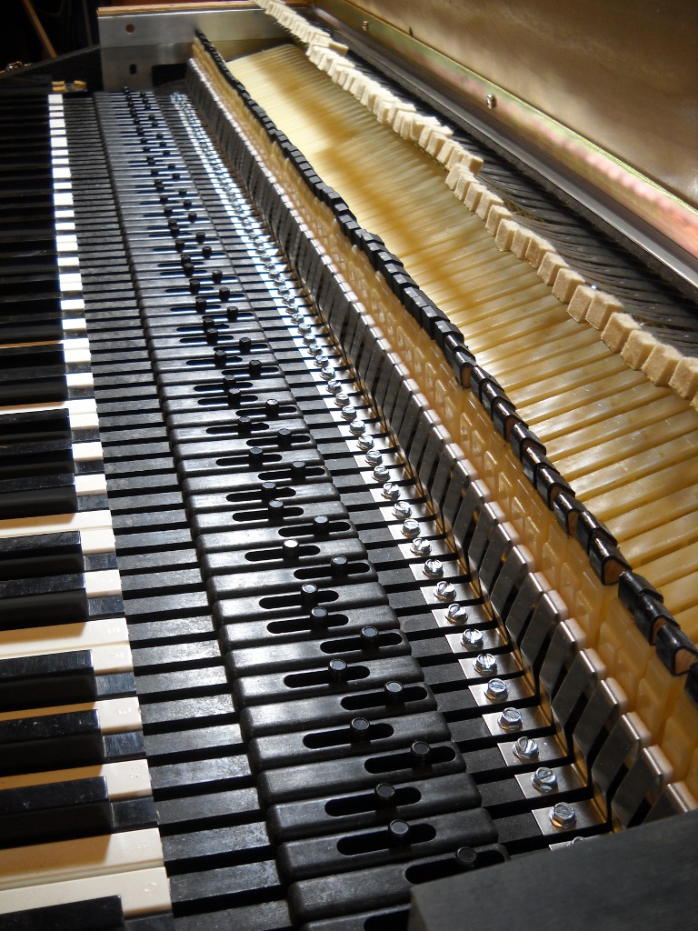
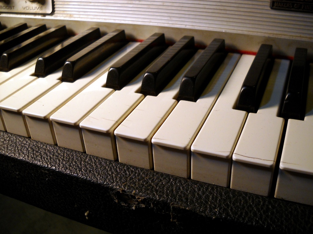
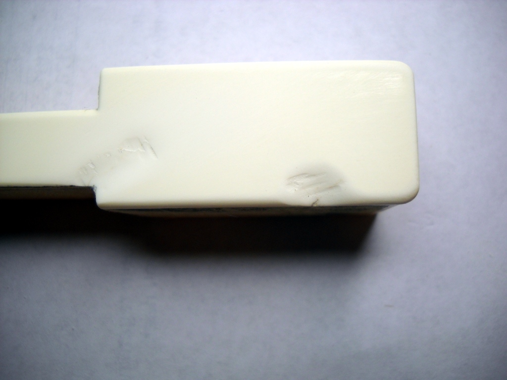
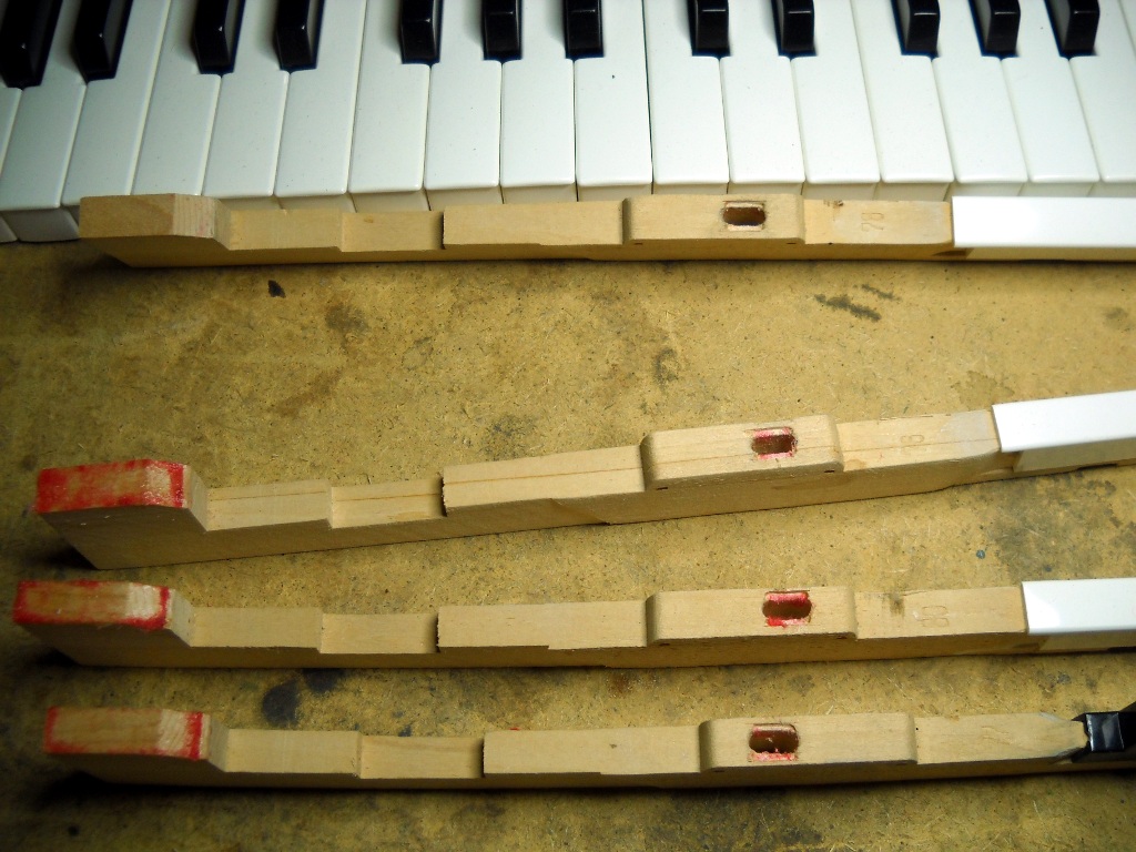
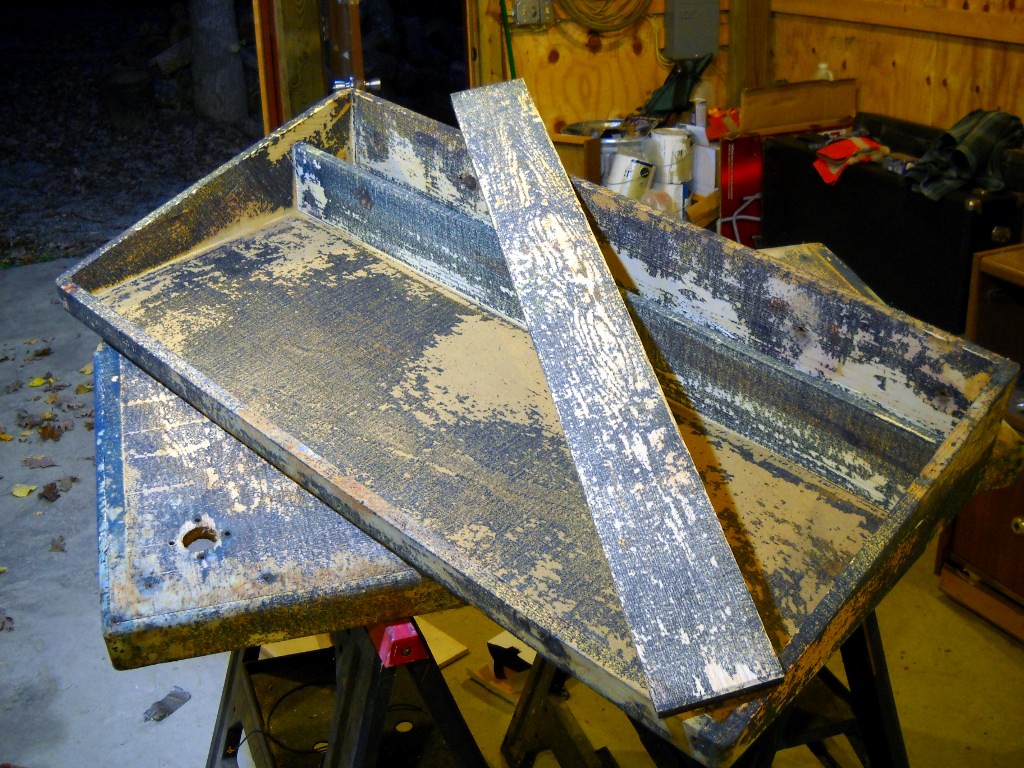
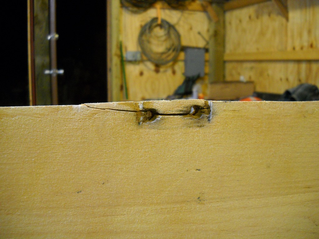
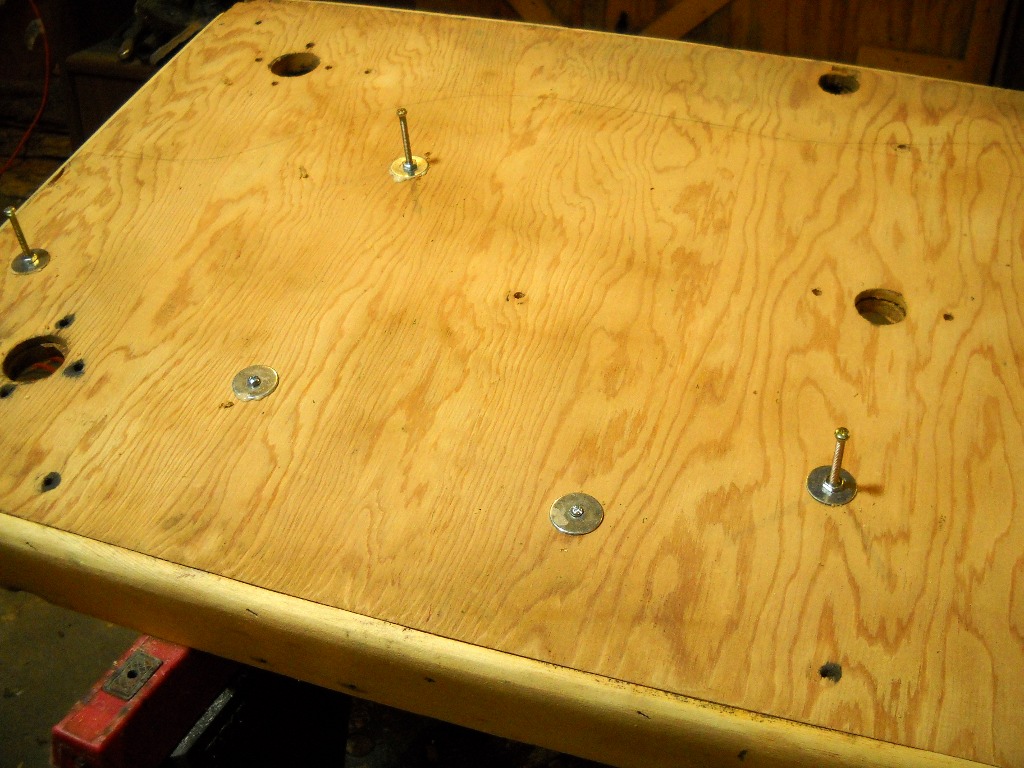
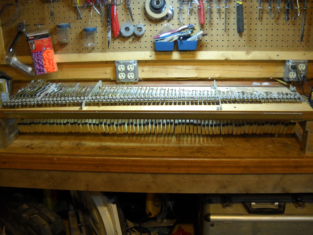
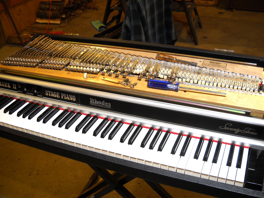
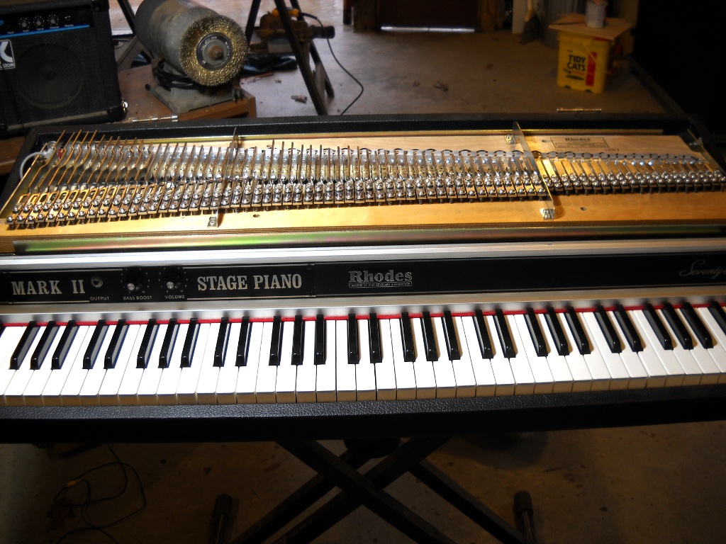
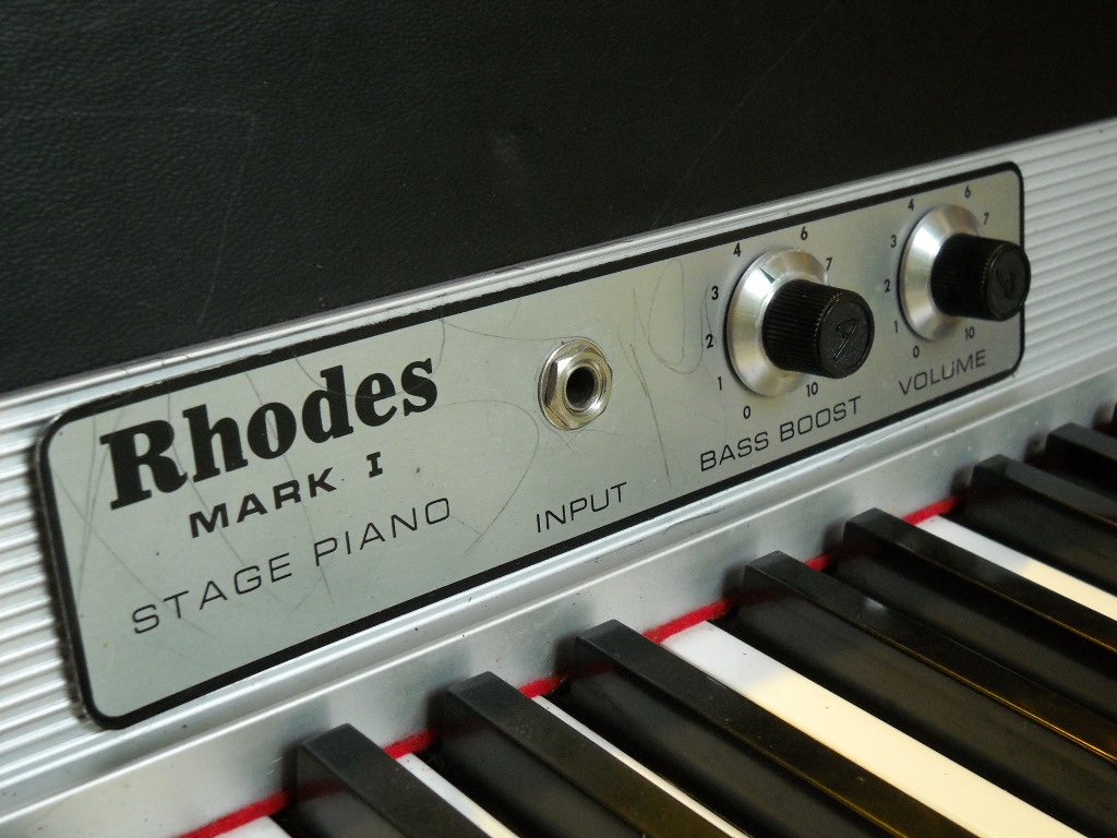
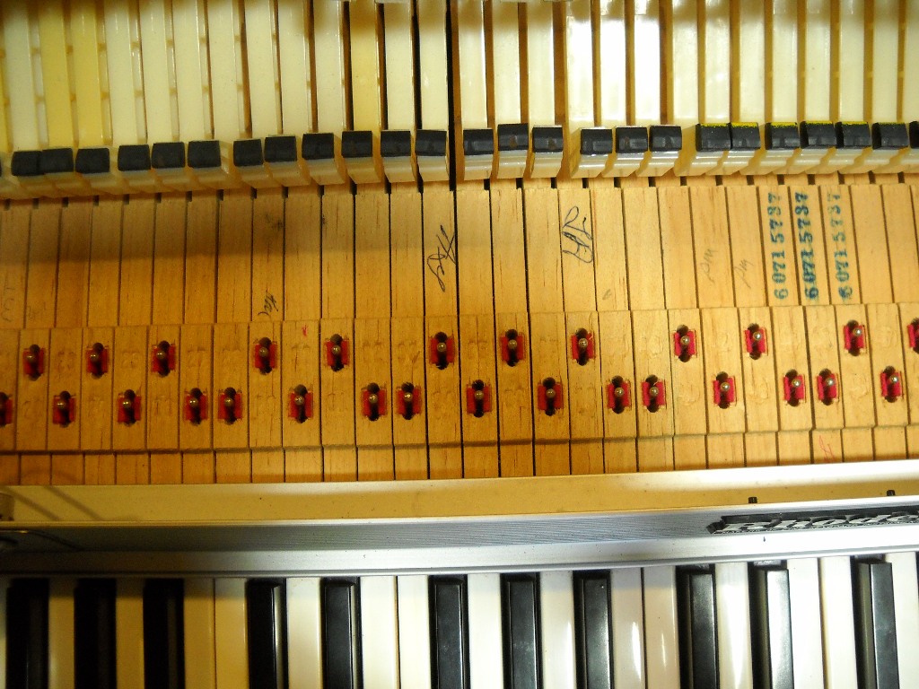
I guess I got lucky with my first three pianos. None of the keys had sustained damage that couldn’t be corrected with abrasives and some elbow grease. According to a regular on the Electric Piano Forum, evidence suggests pianos from the year 1976 suffer from keytops that degrade more quickly than those from other years. I’ve currently got three pianos from that year and two feature craze lines on nearly every key while the third has held together in decent condition.

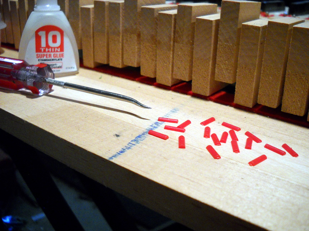
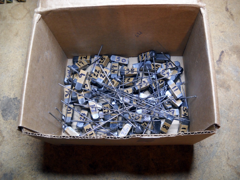
Before committing to replacing an entire set of tops, I first investigated options for repairing the originals. The superficial damage I’d repaired up until then had all been shallow enough that it disappeared after a little sanding. The crazing that infected these keys ran far too deep to make that a viable option. The Rhodes Service Manual provides a recipe for making white glue to use when replacing keytops. This suggested to me that I might be able to devise a similar substance to use as gap filler. My plan was to excavate a crack into a wide furrow that could then be back-filled with my concoction. The pigment for this filler paste was to be provided by ground material from an actual keytop so I first procured a set of sacrificial keys from ebay. After developing several questionable combinations of solvent, powdered keytop and adhesive, I finally concluded that this was not going to be a practical solution. Even when I was able to mix a batch that set up properly, my closest color match still left a shadow that was just as obvious as the original crack.

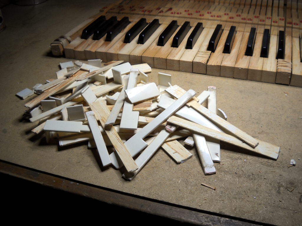
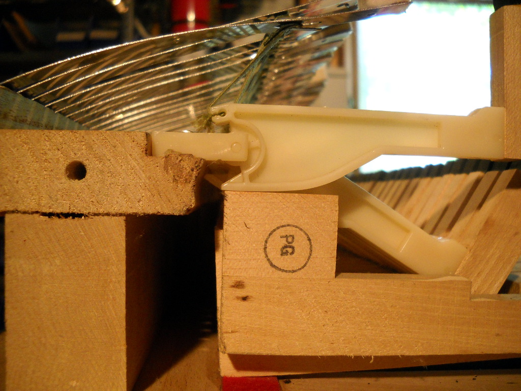
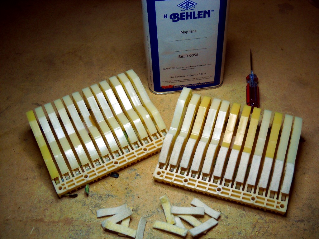
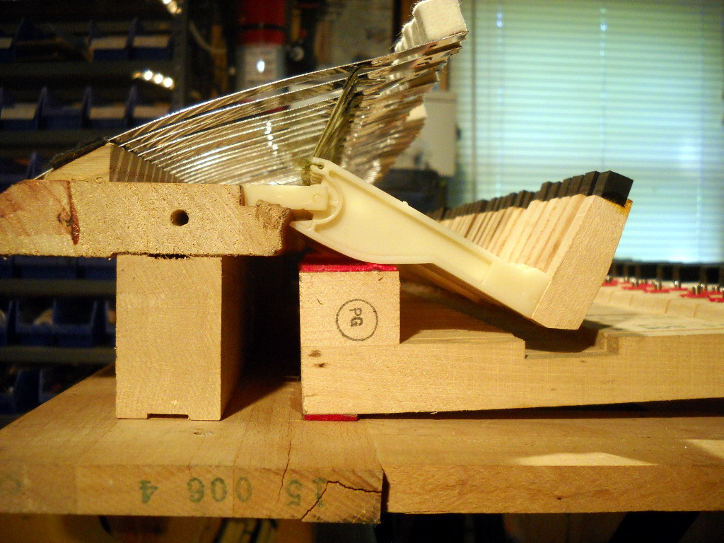
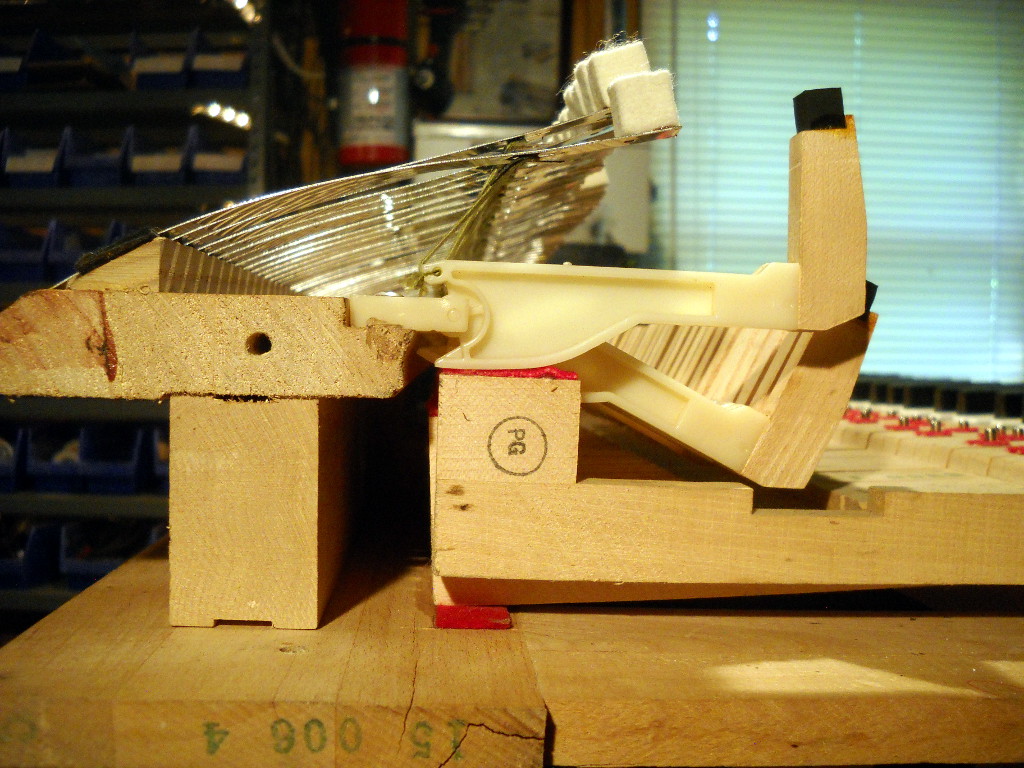
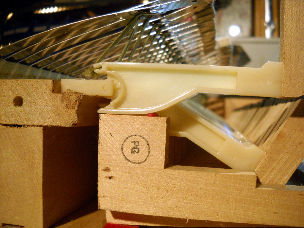
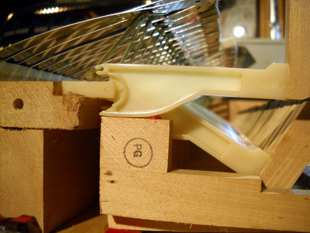
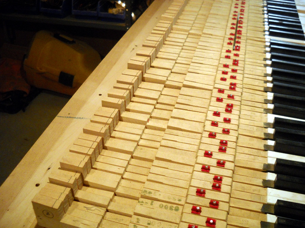
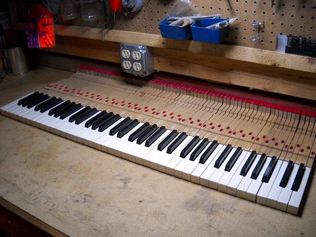
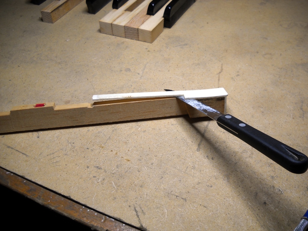
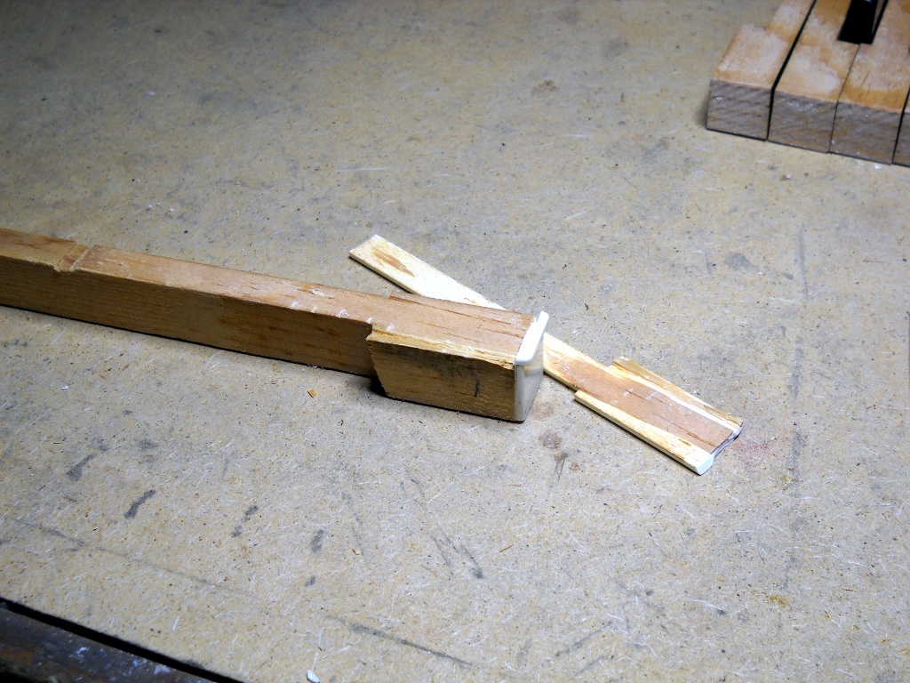
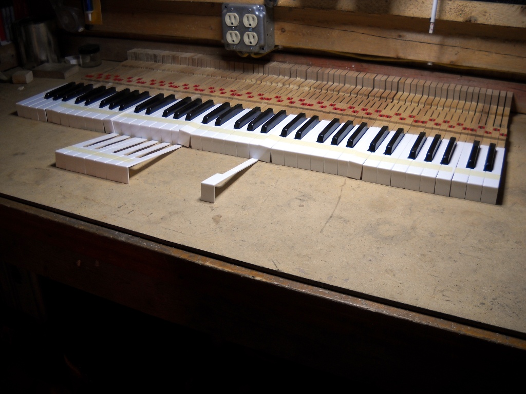
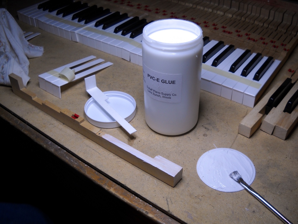
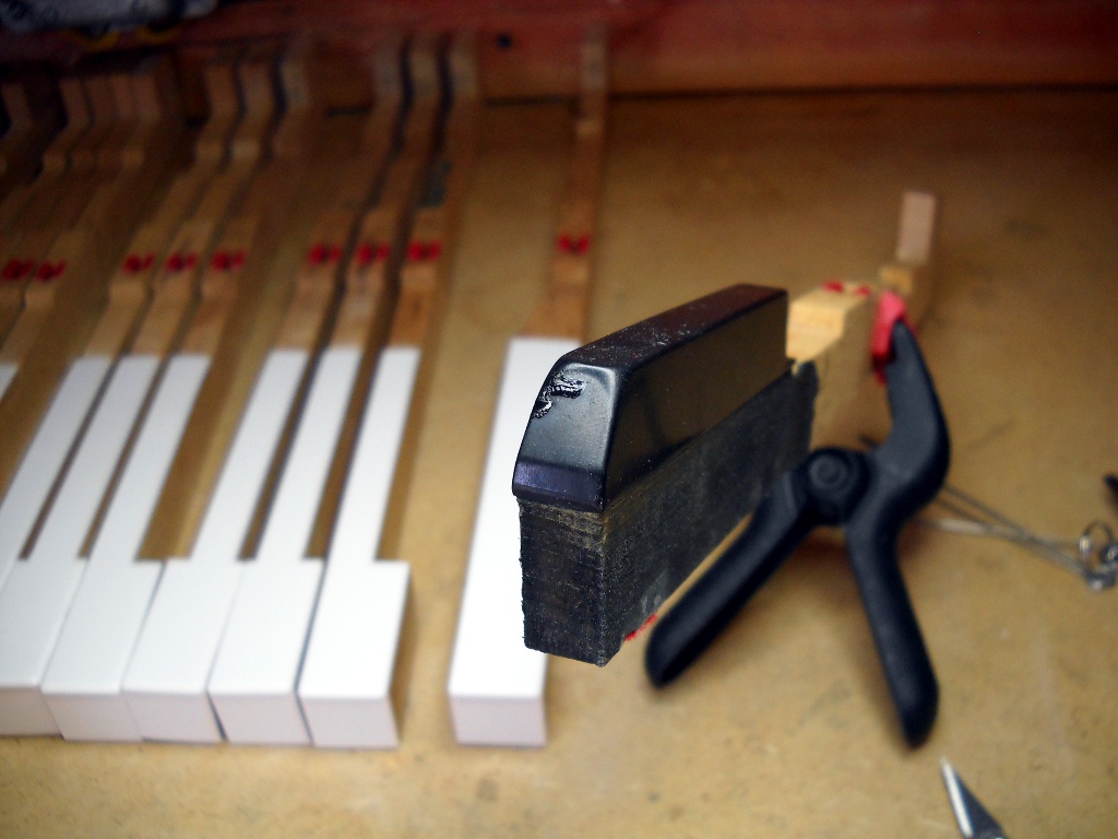
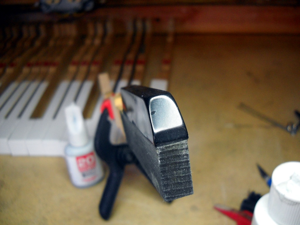
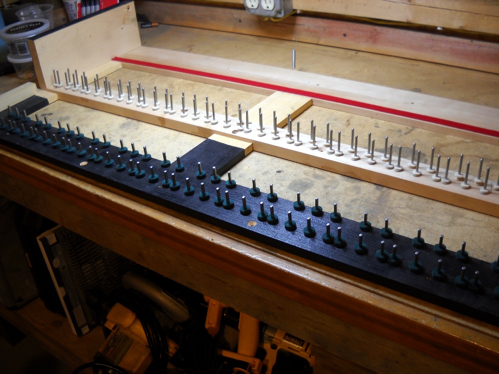
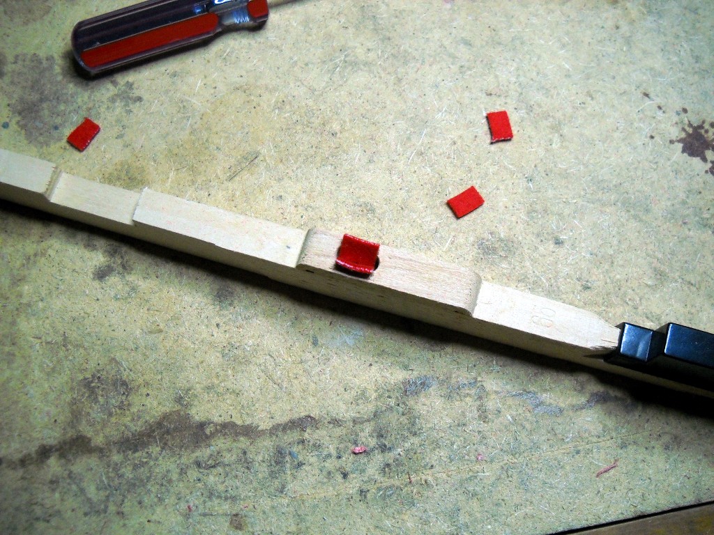
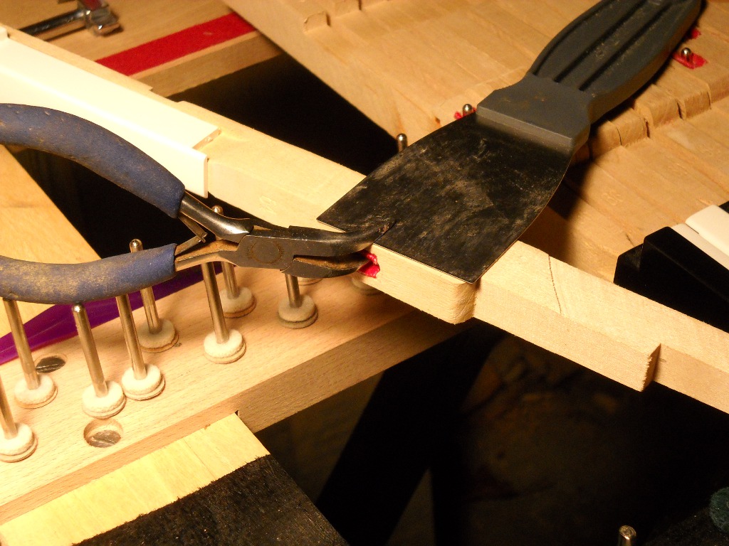
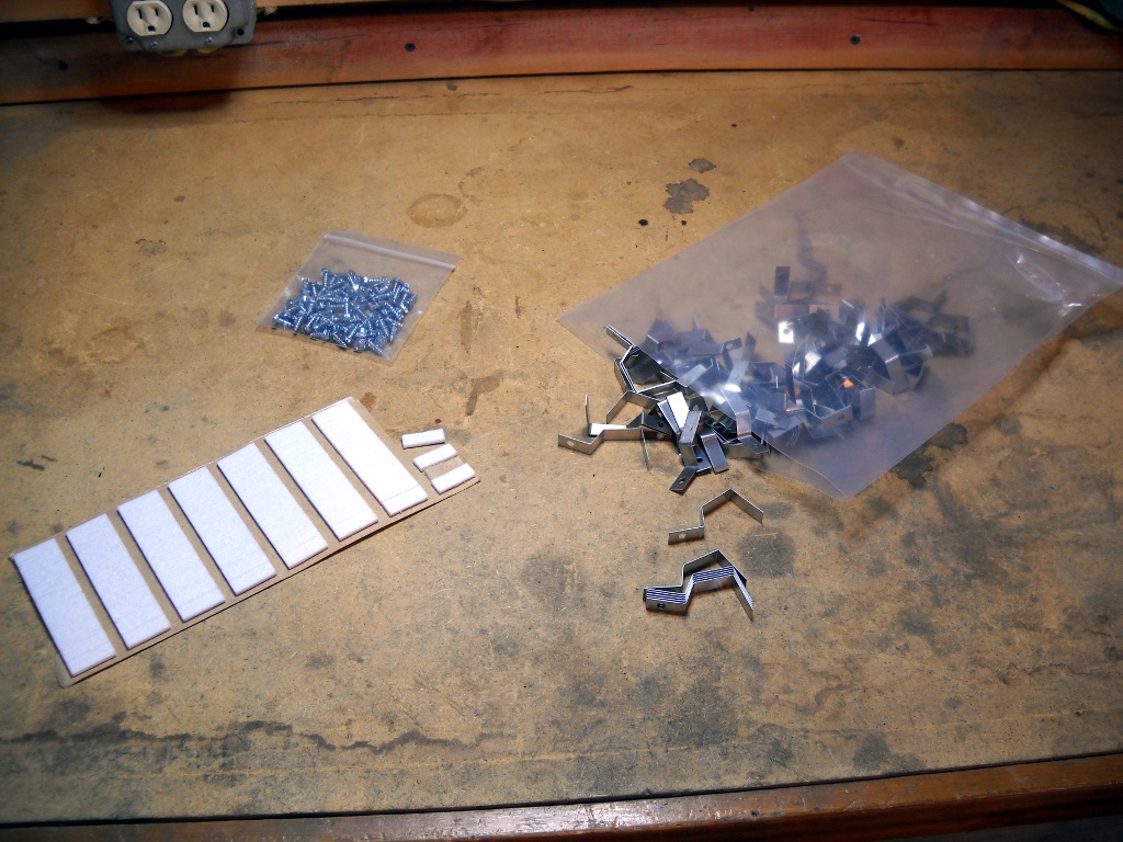
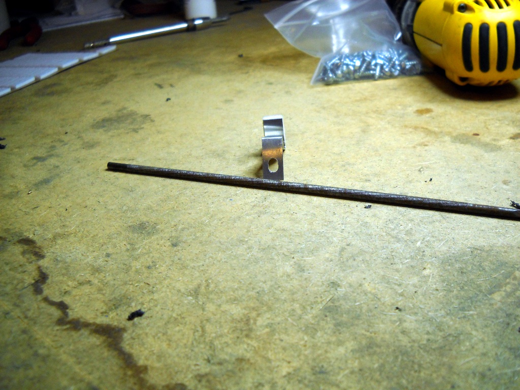
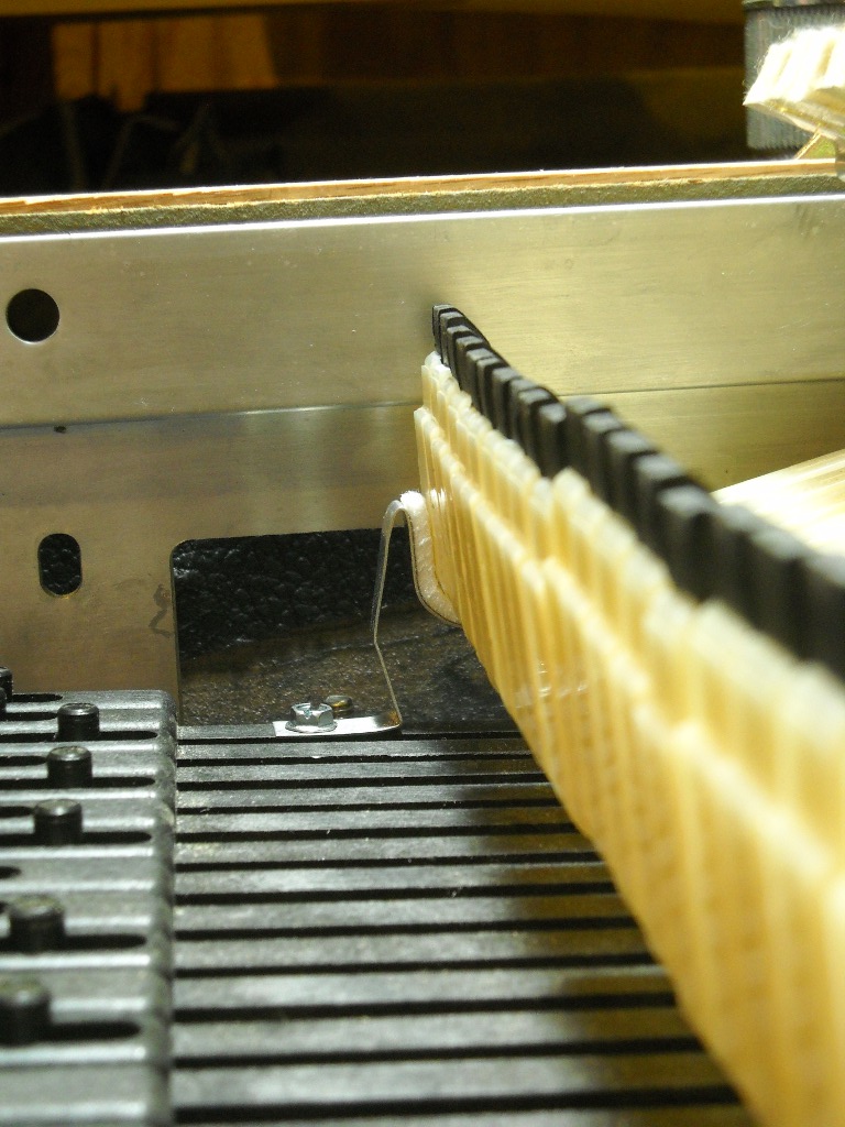
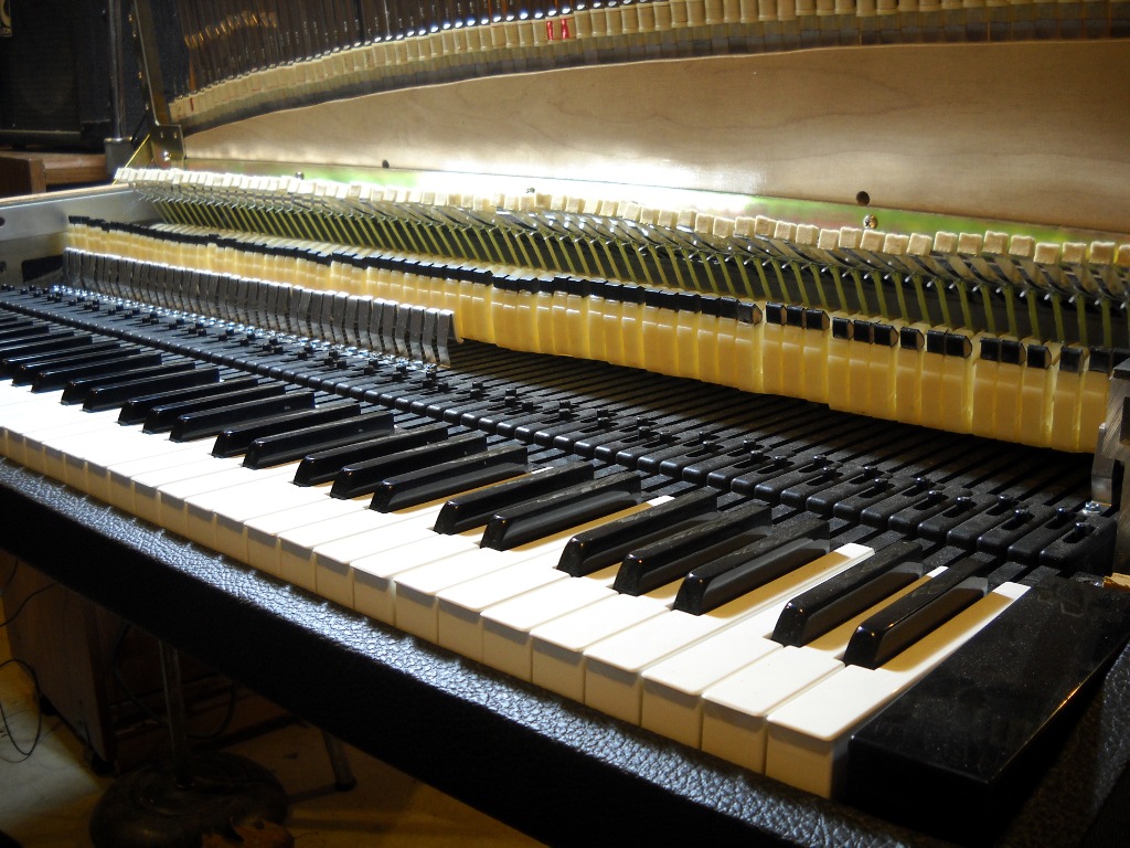
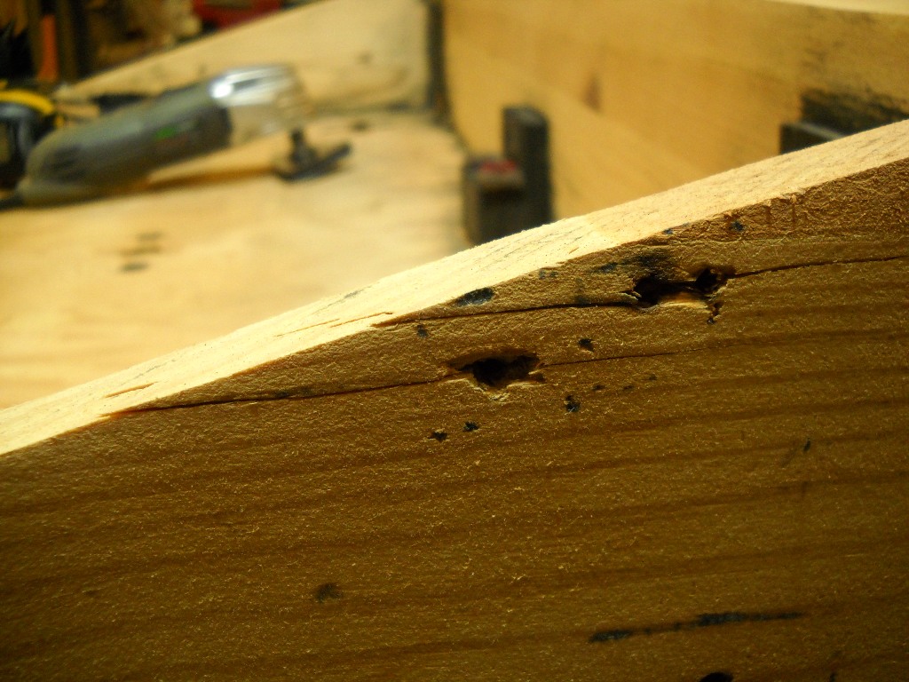
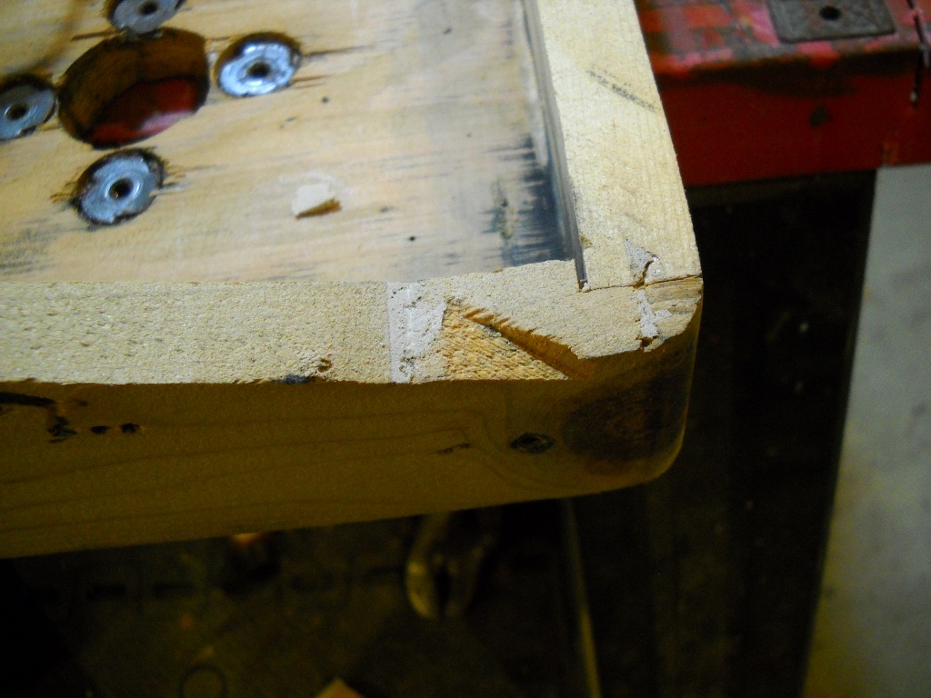
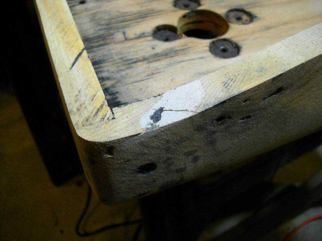
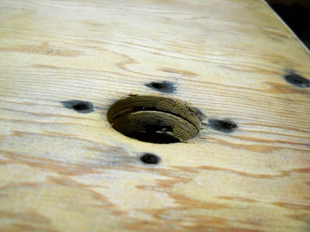
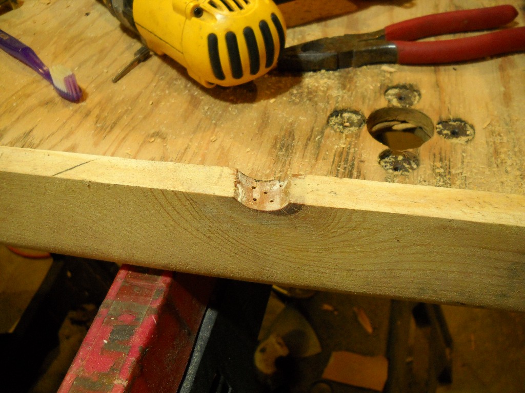
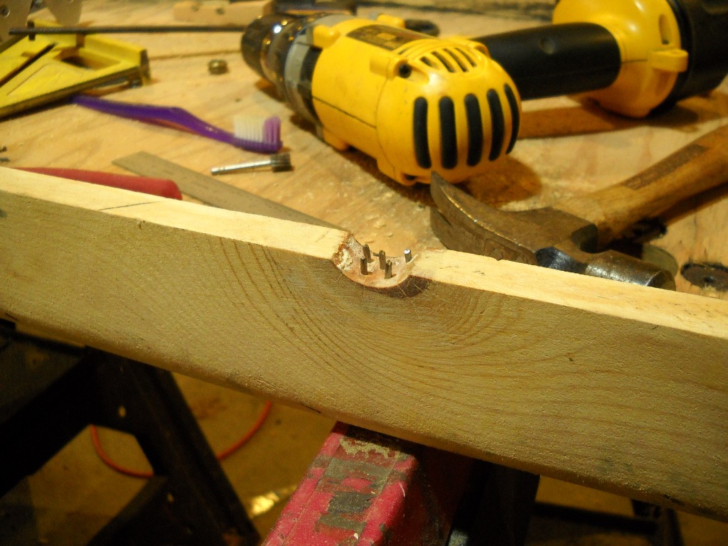
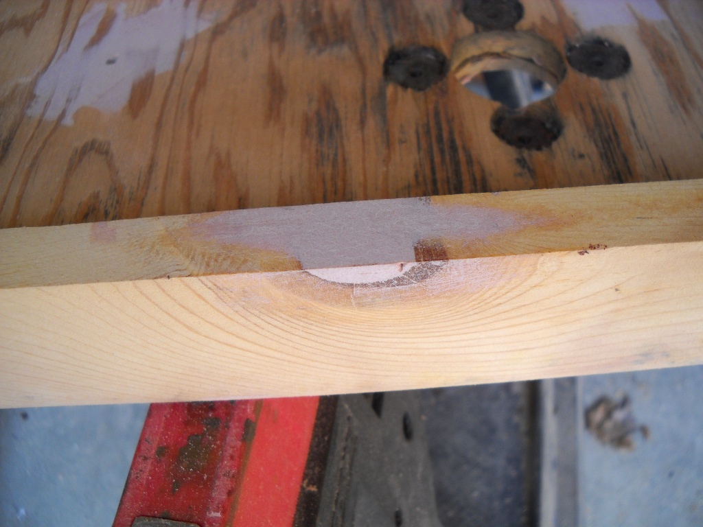
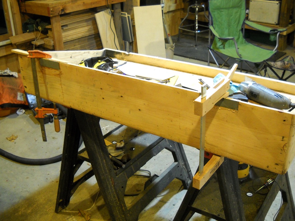
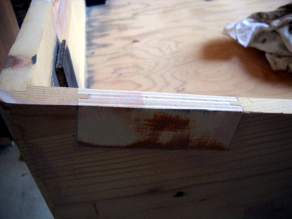
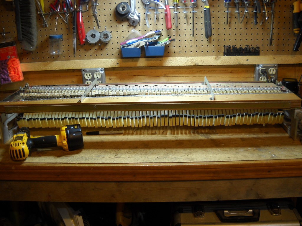
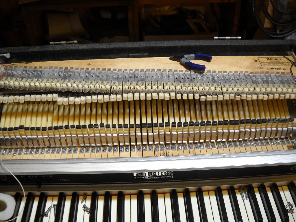
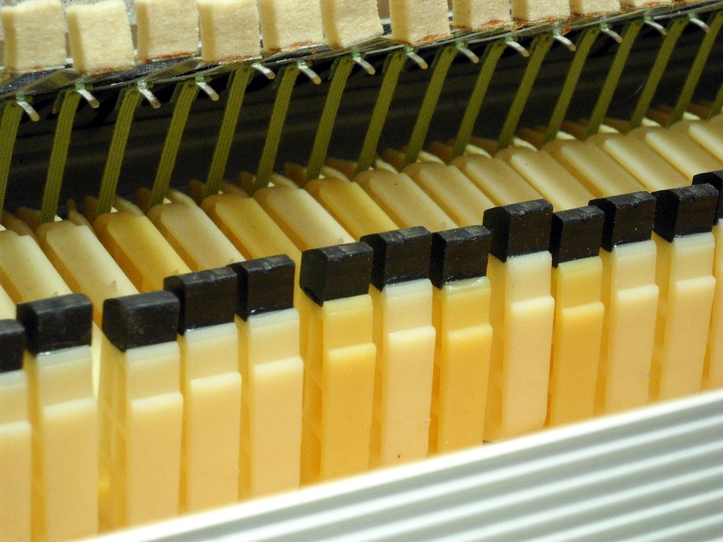
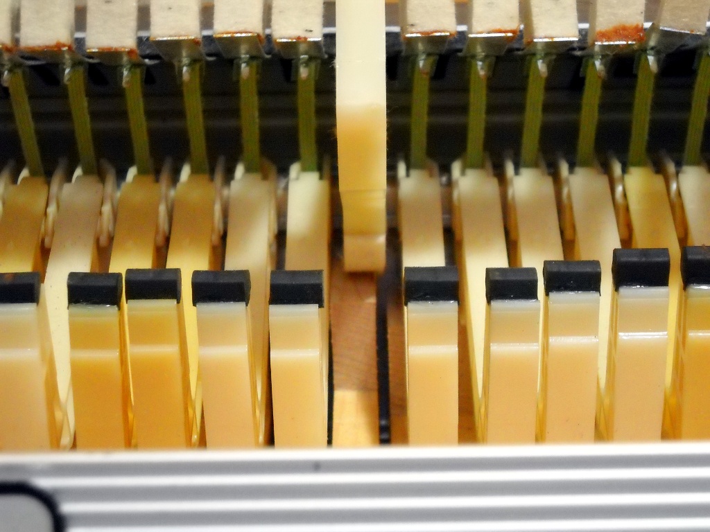
An old kitchen knife made a good tool for removing the original tops.1 Although the plastic mostly came up easily, on several keys it insisted on taking some wood with it leaving voids that I later had to fill with Bondo.2 The replacement keytops, manufactured by Schaff Piano Supply, were not exact matches to the originals. In addition to being intentionally oversized to fit a range of key sizes, the overhang in front was less pronounced than on the factory keys. After being glued down, the tops could be trimmed to fit the keys but the shorter overhang would have to do. They’re sold in sets of 52 which provided a few spares in case the first installation attempts didn’t go my way.

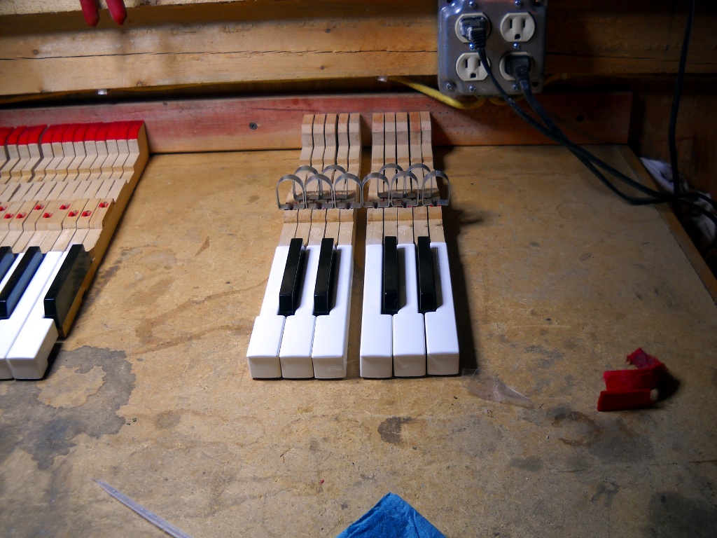
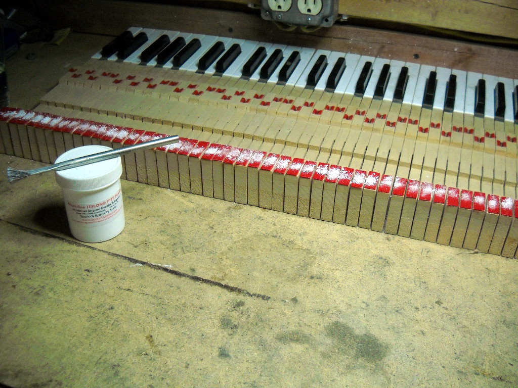
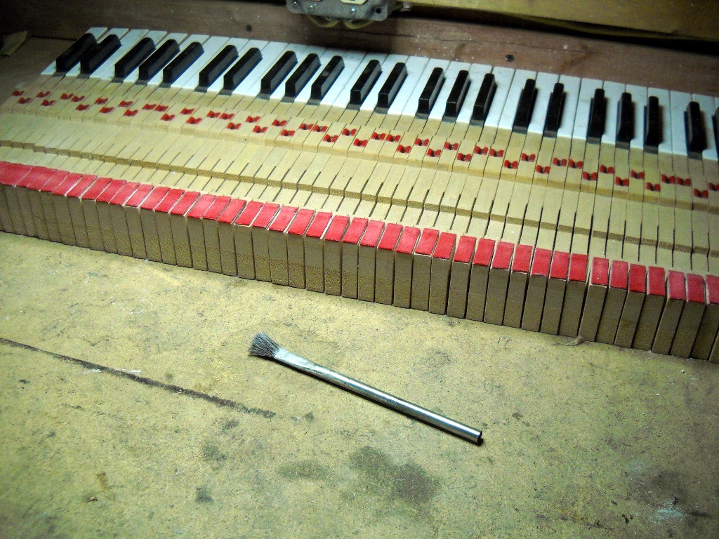
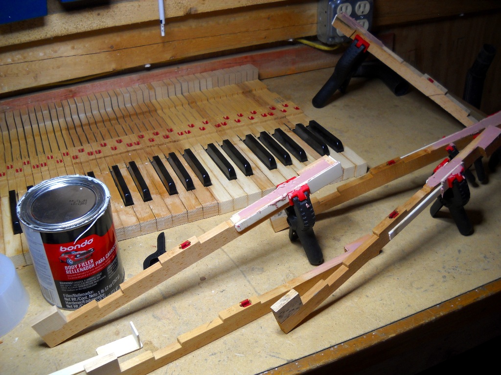
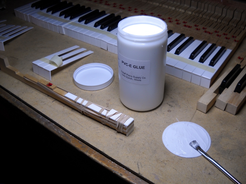
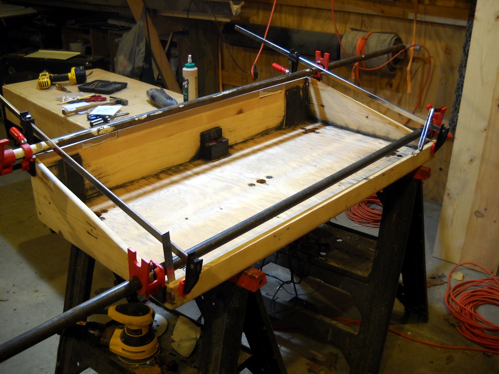
The new keytops were attached using PVCE glue. Not at all like PVC glue used for plumbing applications, PVCE looks and spreads like household white glue. It excels at bonding porous to non-porous surfaces as when attaching plastic to wood. The glue was spread thinly across both the key and the top and the two parts were joined immediately. Excess glue was squeezed out of the edges and wiped away with a damp cloth then the whole assembly was wrapped as tightly as possible with four or five rubber bands. The wet glue allowed the top to be repositioned but held well enough that it stayed put once properly located.

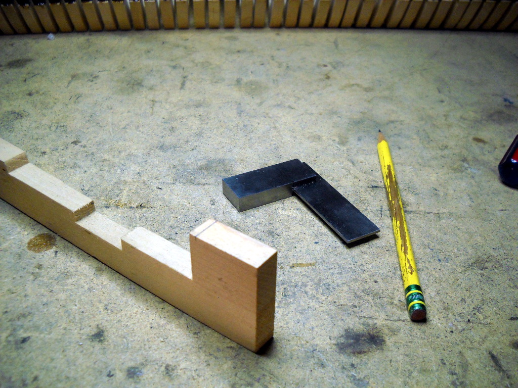
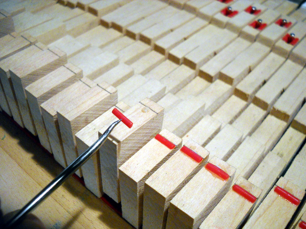
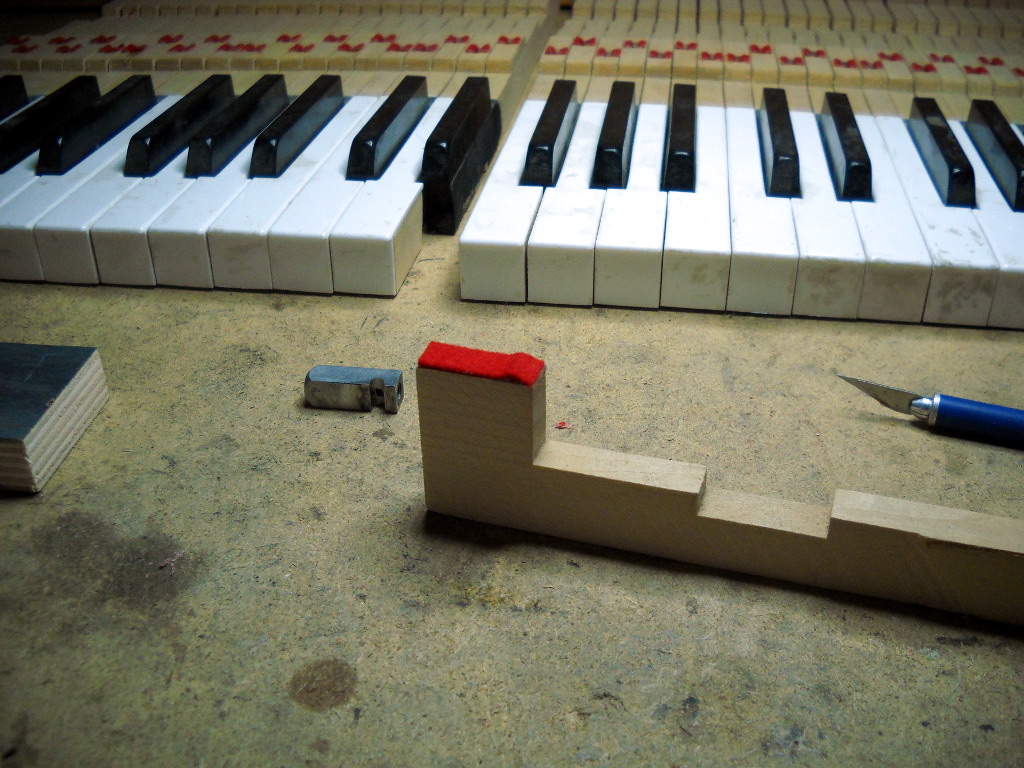
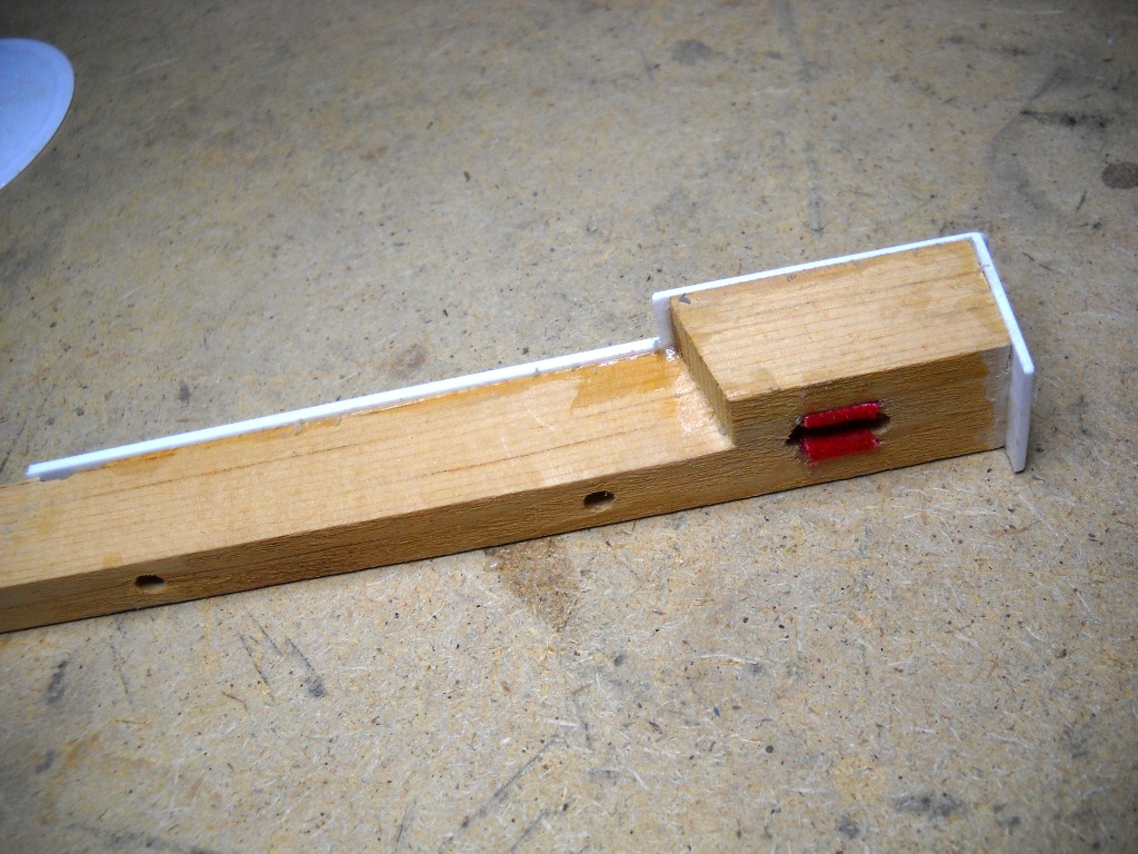
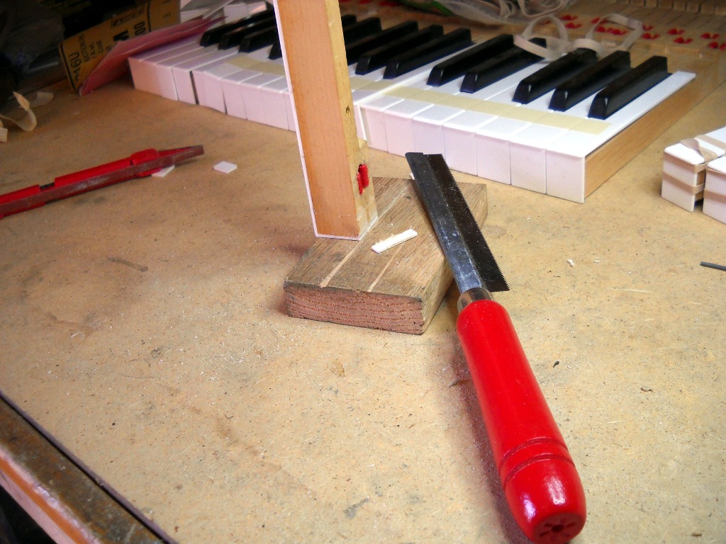
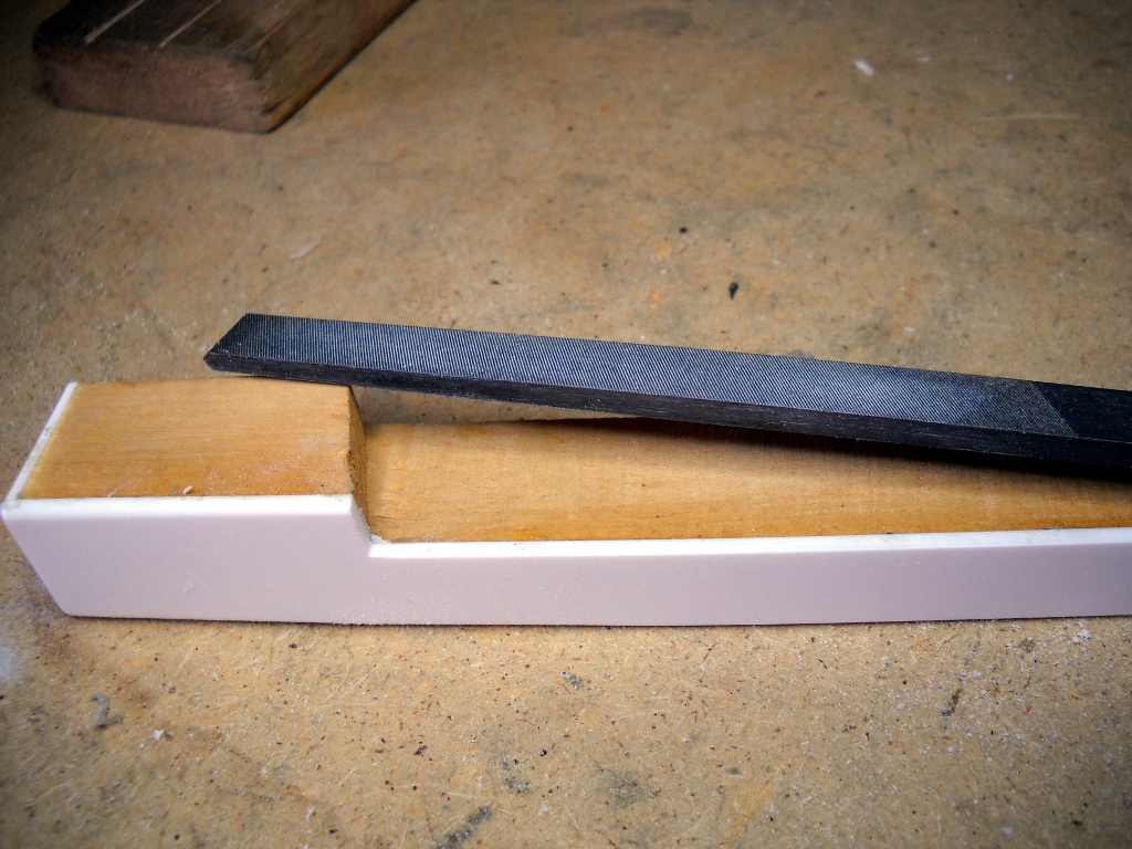
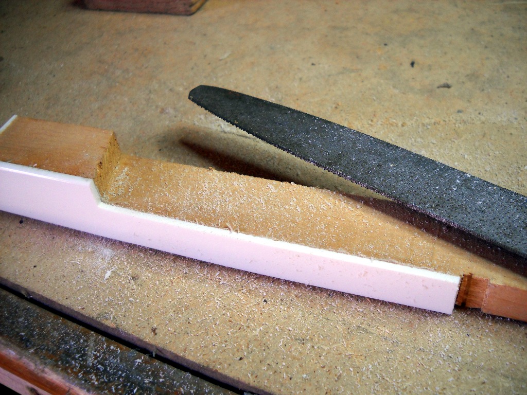
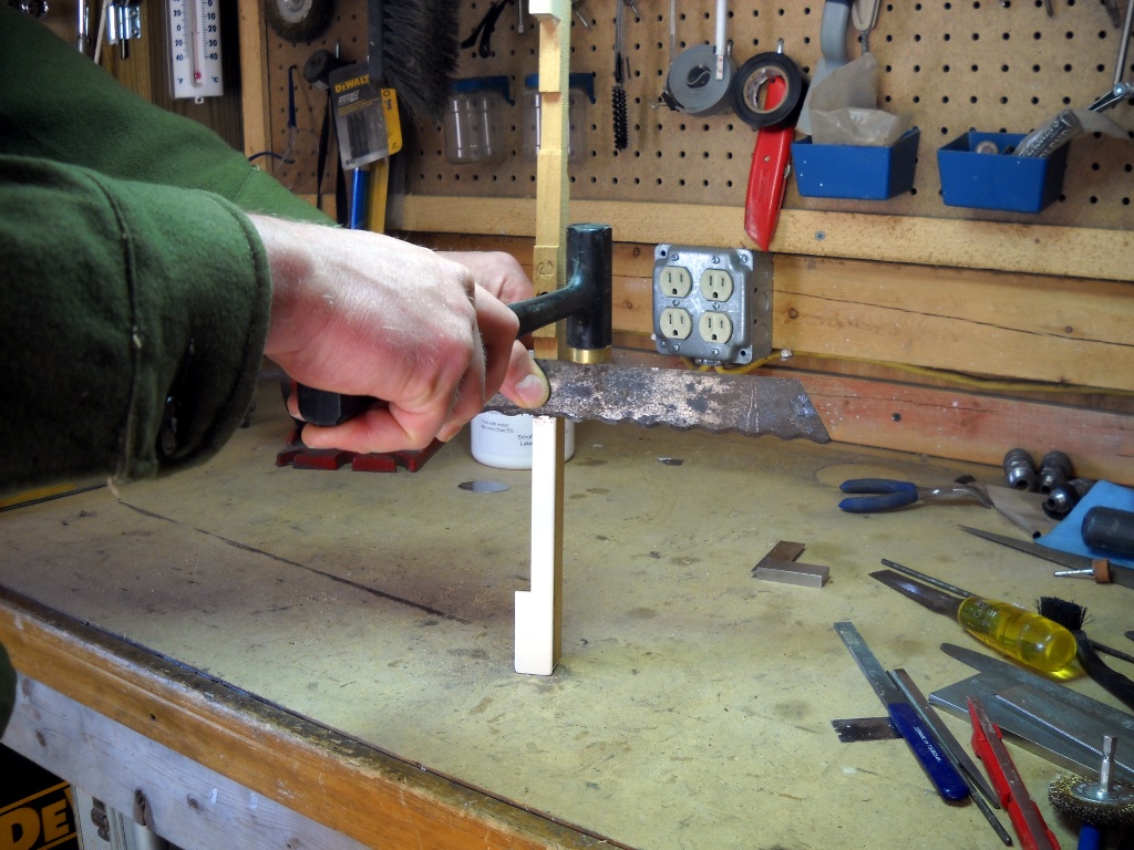
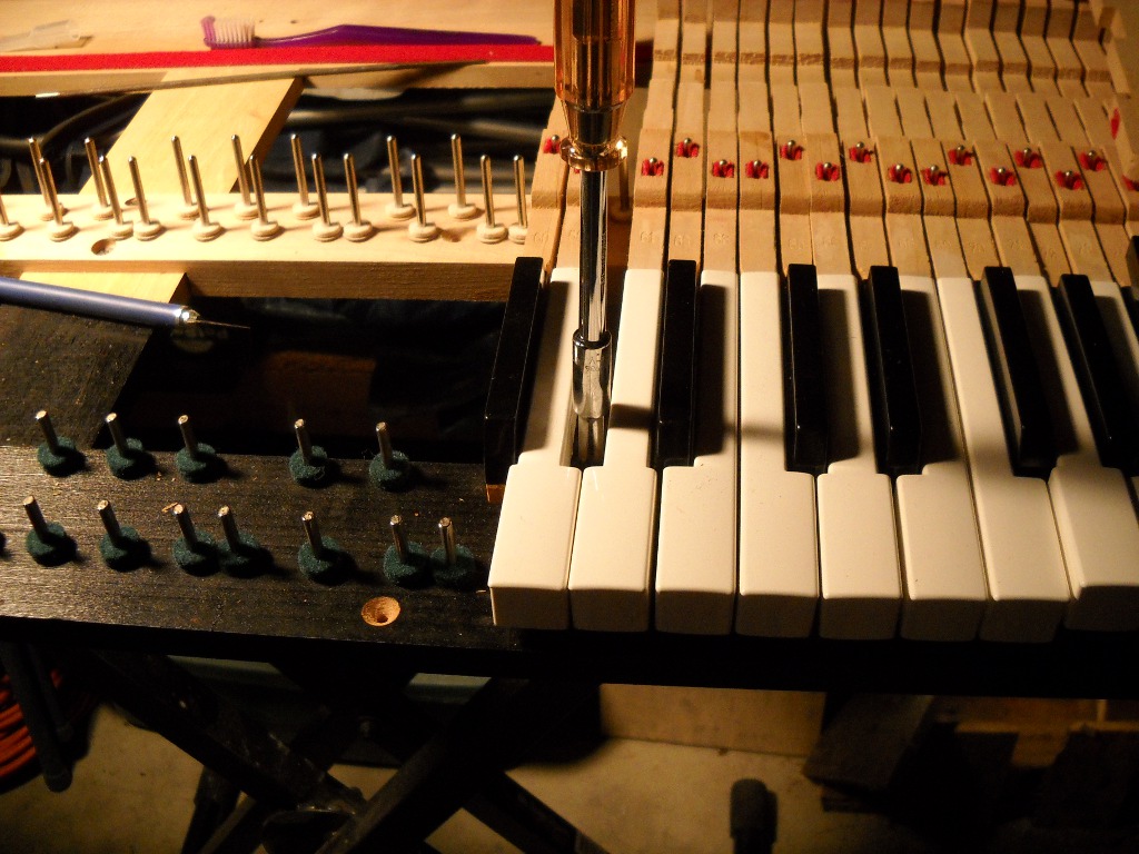
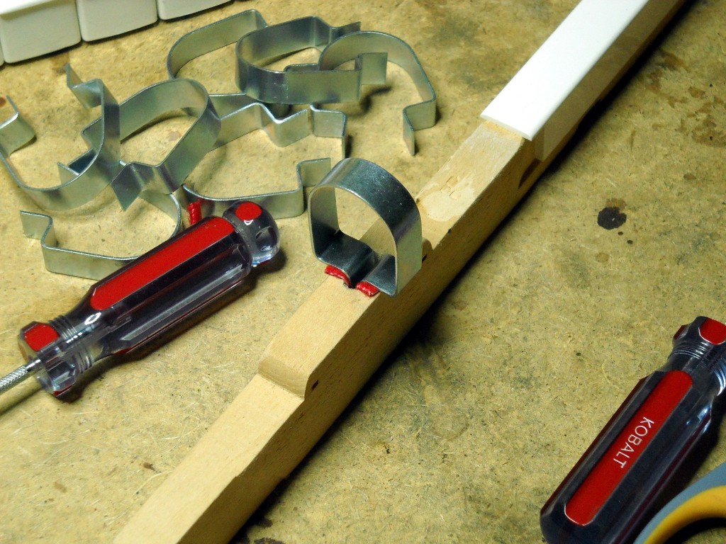
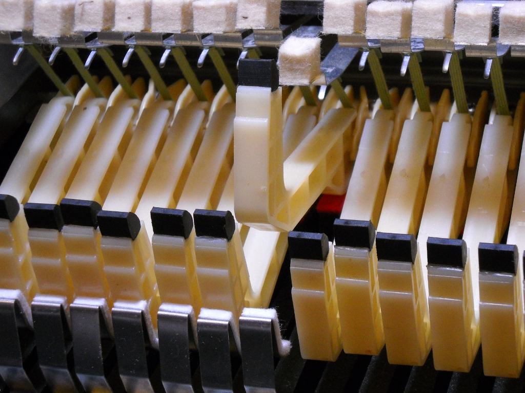
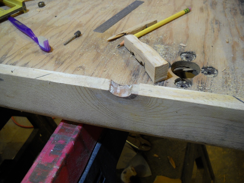
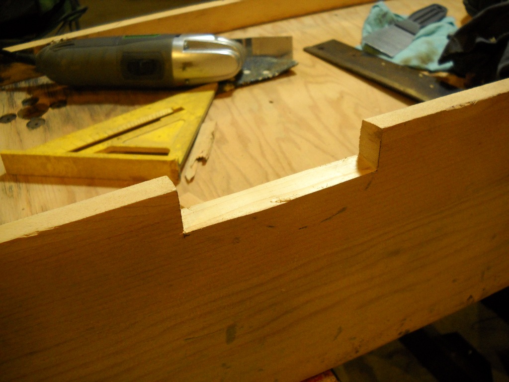
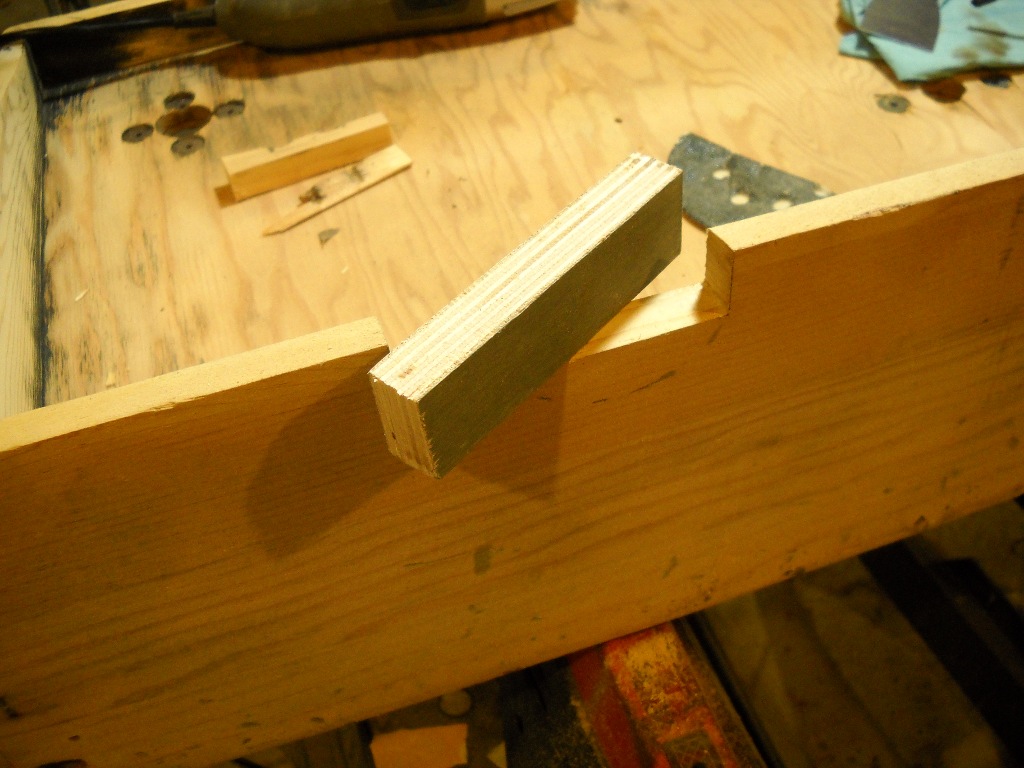
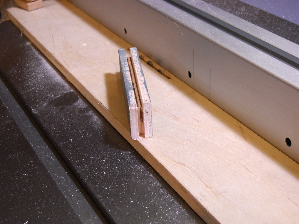
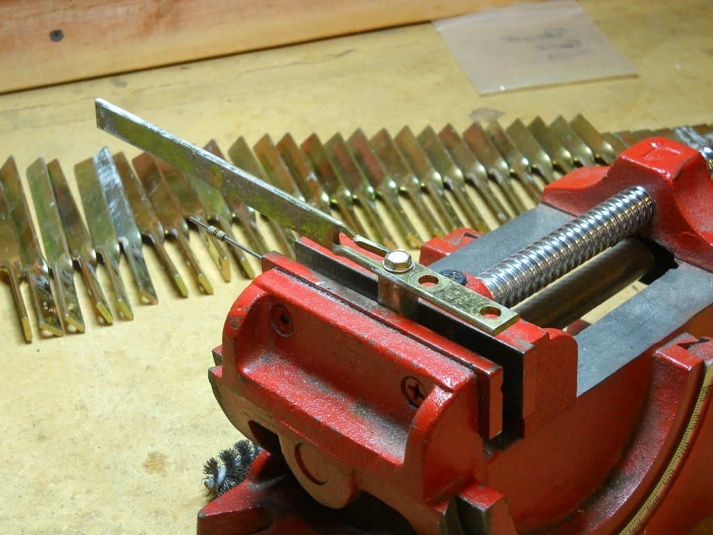
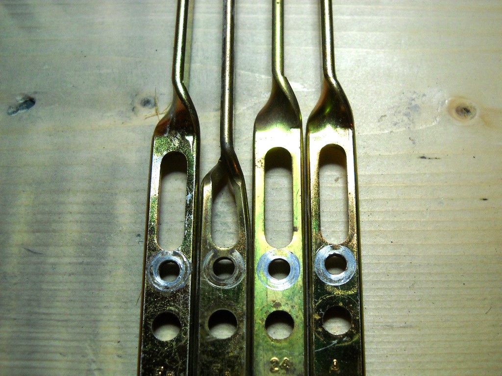
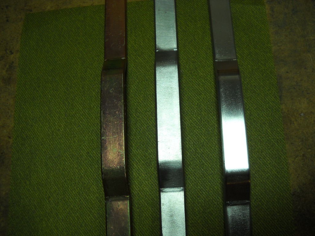
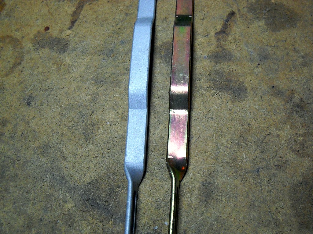
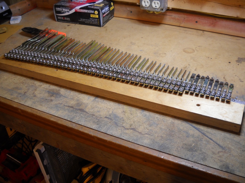
The tops were installed unaltered and later trimmed down to fit the key. First, the excess lengths of the tails and fronts were removed with a small handsaw. The heads fit the width of the keys perfectly but were far too long requiring their shoulders to be filed back quite a bit. Some of the tails fit more closely than others. Most of their edges were scraped with a rasp then finished with a smoother file to bring them flush with the sides of the keys.

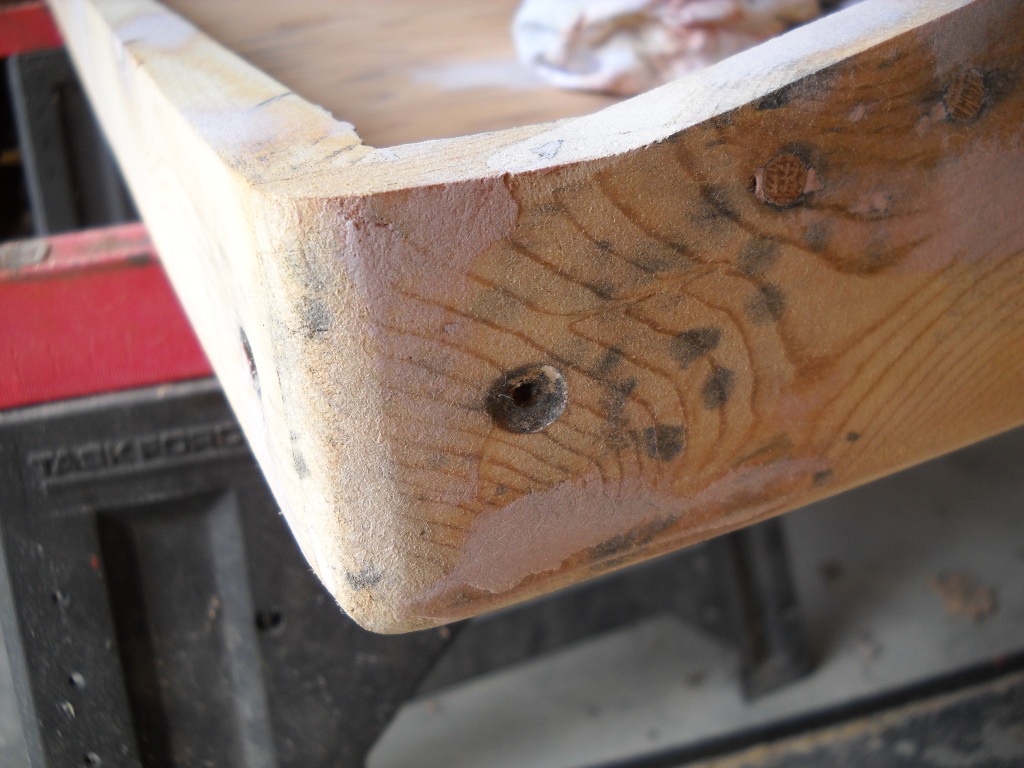
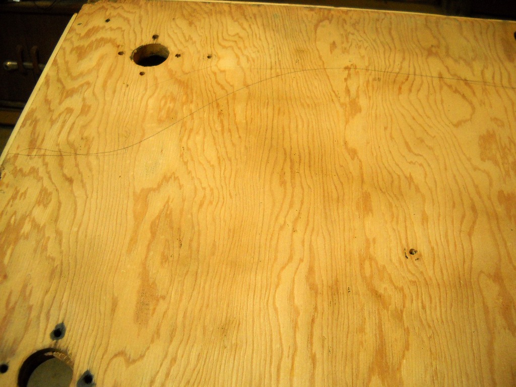
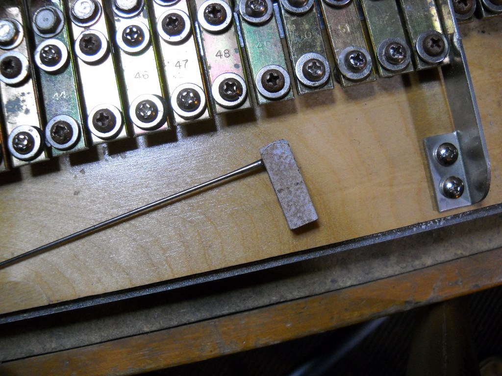
At first, I referenced the underlying wood to determine where to cut and file each key but that resulted in uneven lines both at the tail ends and, more visibly, along the keys’ shoulders. Before proceeding, I remounted all of the keys on the keyframe and used a pencil and a straightedge to make reference lines that would remain consistent from key to key. This approach worked much better and the remaining keys maintained noticeably cleaner lines.

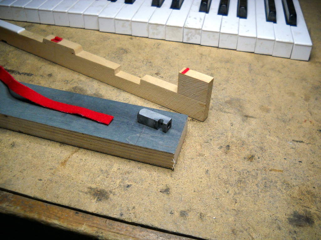
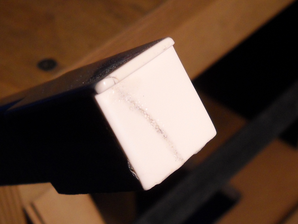
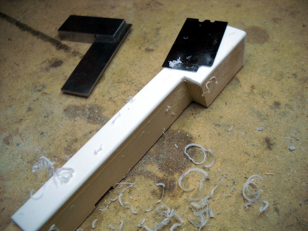
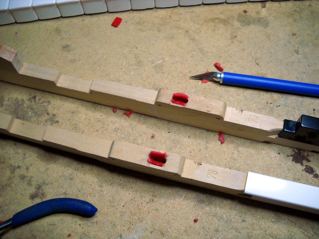
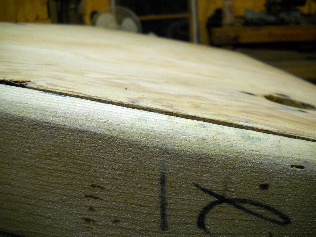
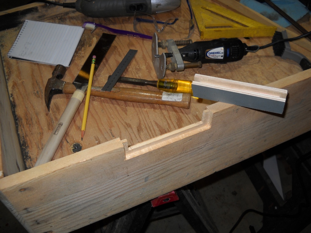
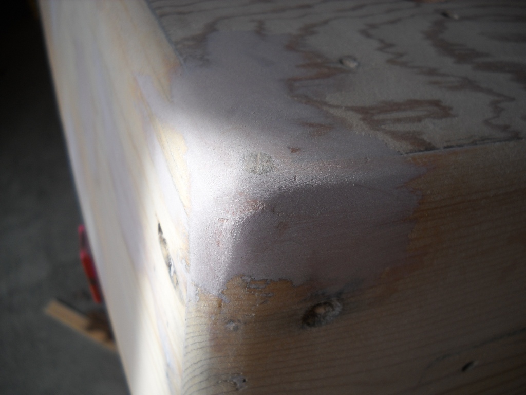
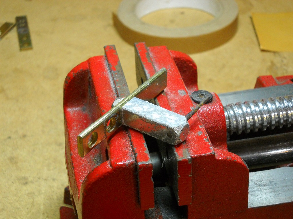
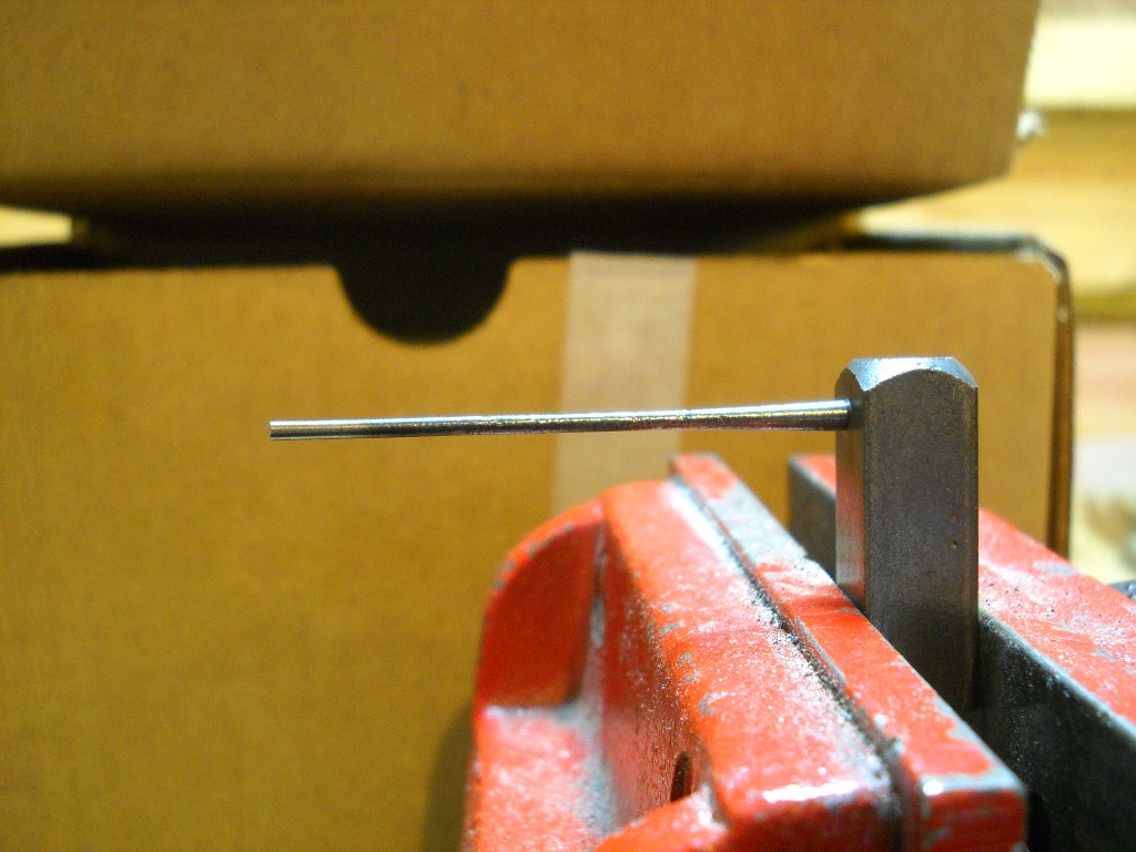
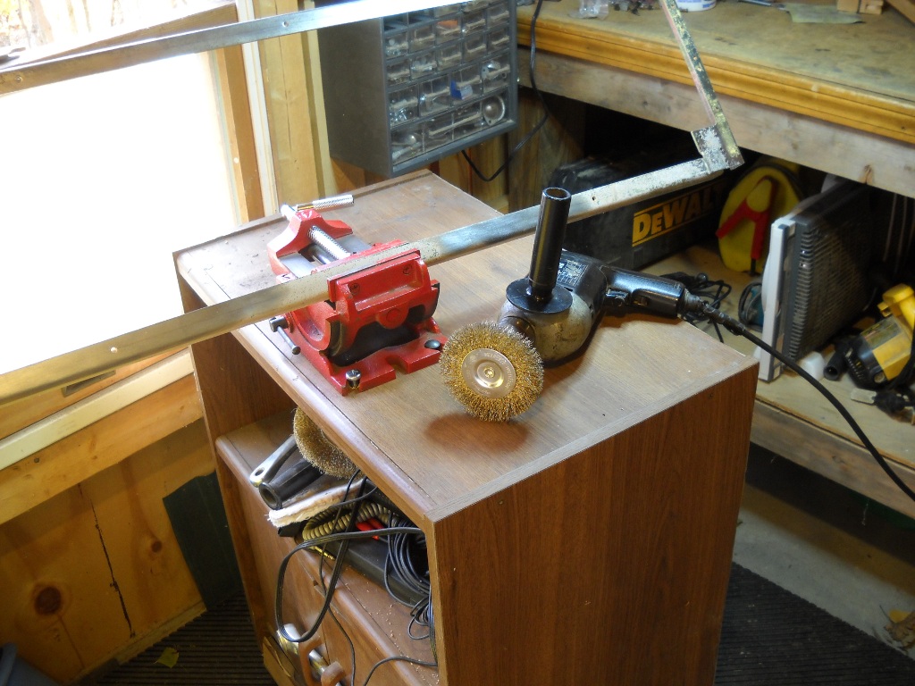
The tops were supplied with edges finished with a smooth chamfer. Unlike on the original keys, the new chamfer kind of dwindled as it ran along the edges of the tail. Additionally, most keys required enough work with the rasp that their factory edges were obliterated. To restore the chamfer, I used files designed to be used on guitar frets. These files feature concave cutting surfaces that matched the radius of the key edges very well. Not designed to cut plastic, the files loaded up quickly and required patience to do their work but the result was a nice even edge that required little or no follow-up dressing.3

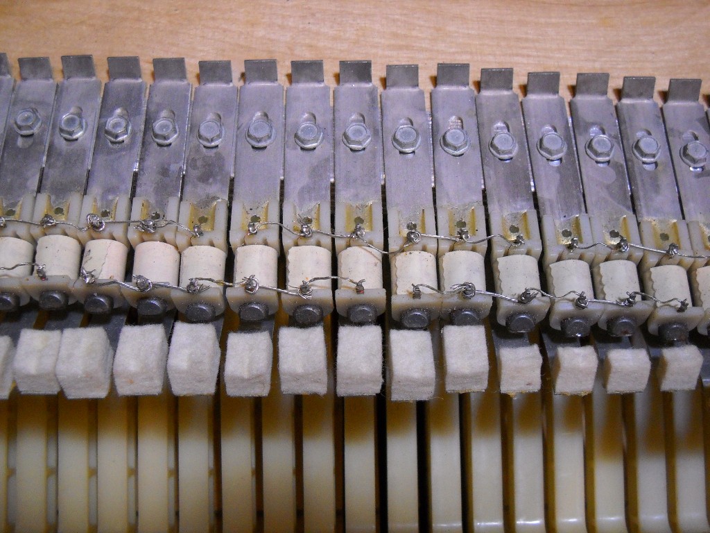
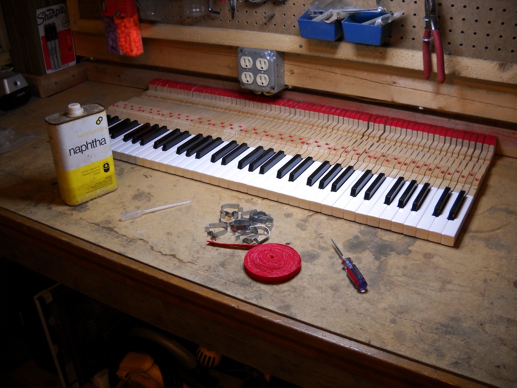
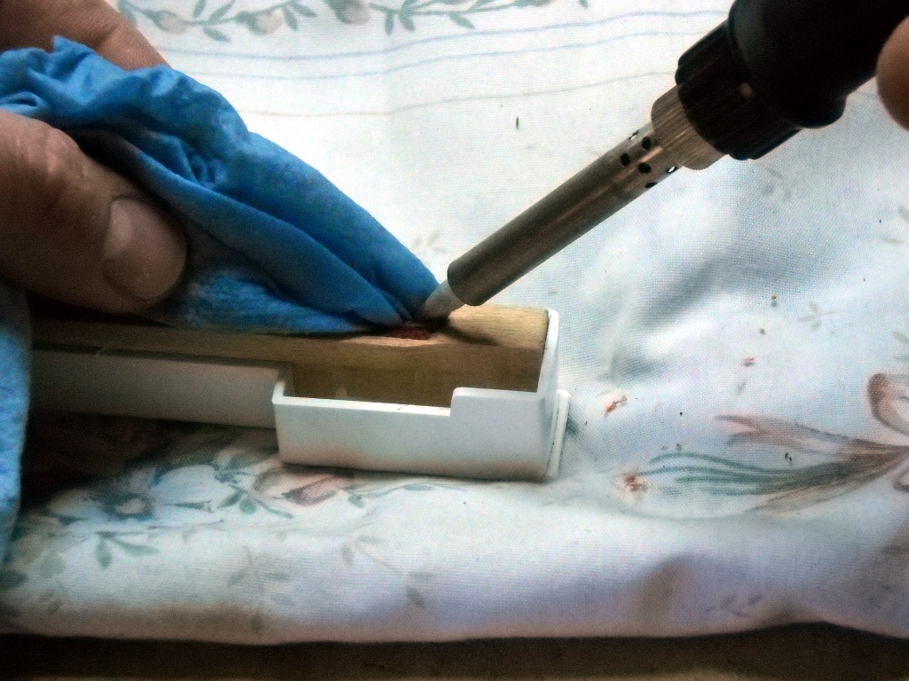
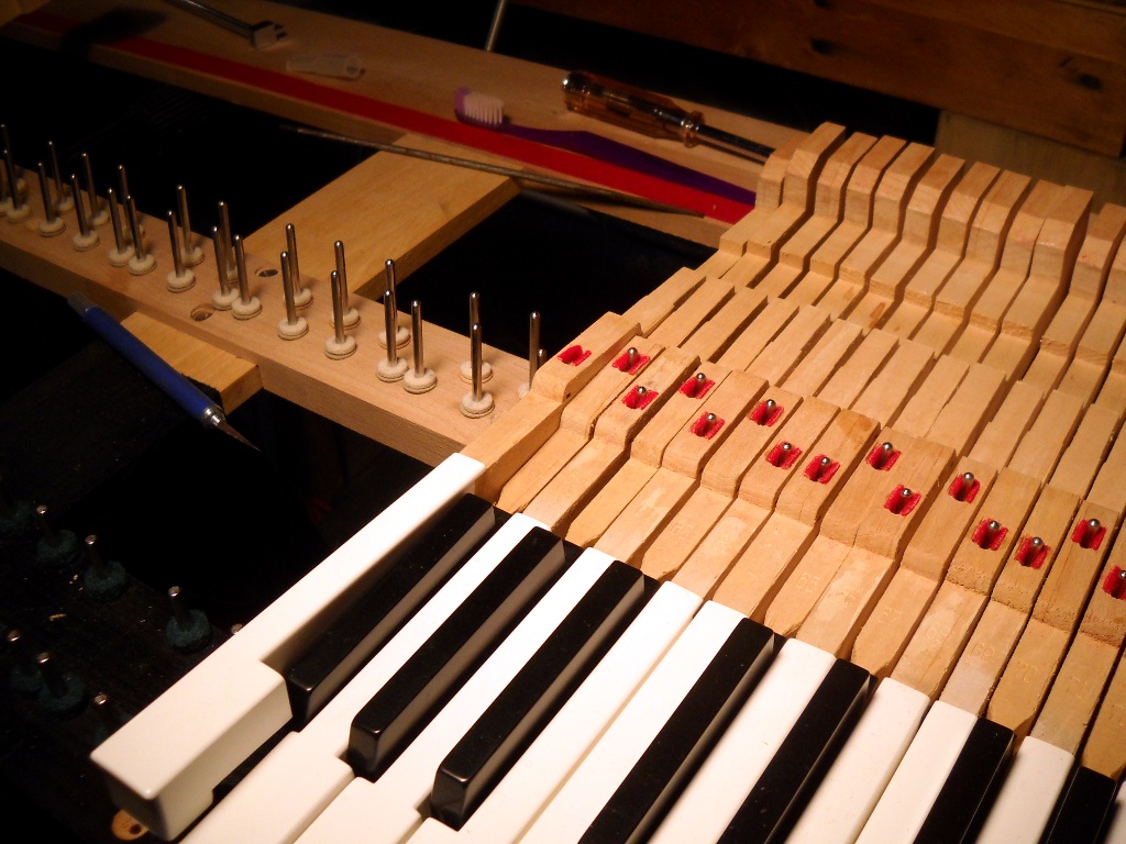
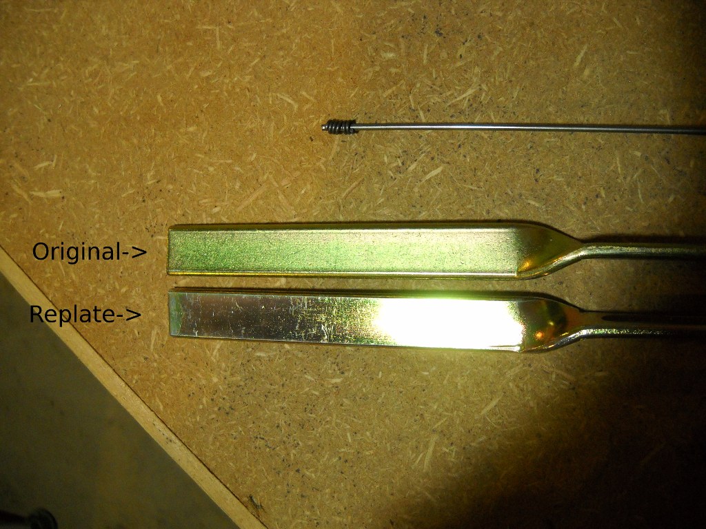
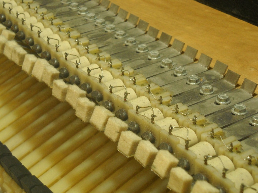
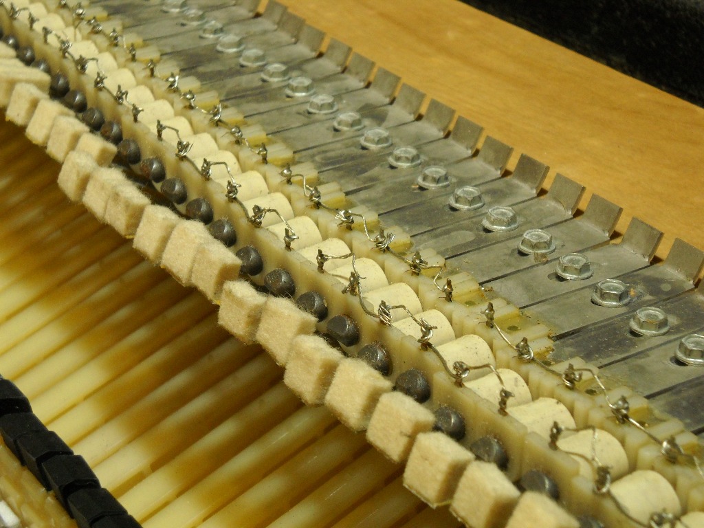
The black keys don’t seem to commonly suffer from the same crazing that plagues white keys. The sharps for this piano were no more damaged than those of any previous unit I’d worked on although they did have one or two visible chips to be repaired. As I’d done with reasonable success in the past, the damaged areas were filled with black super glue. After sanding and polishing, the fill was indistinguishable from its surroundings unless it caught the light in just a certain way.

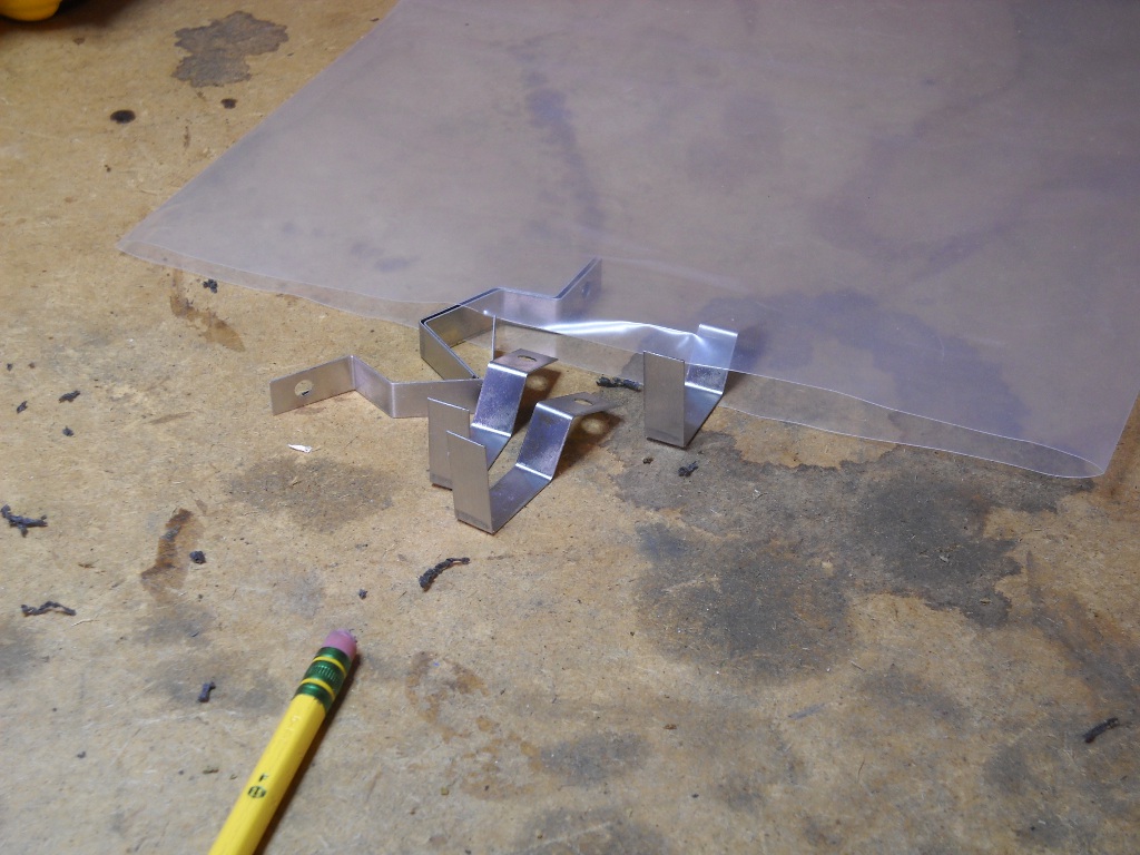
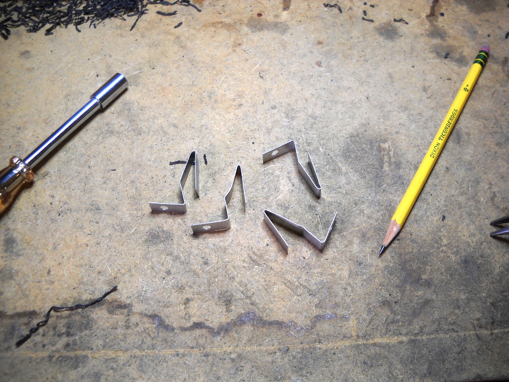
1I now use a much larger tool that appears to have been a bread knife in a former life. Holding the key upright on its face, I tap the knife down between the top and the wood.Return

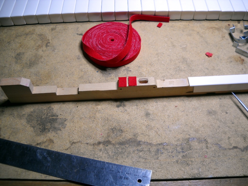
2For filling gaps in keys, I’ve begun using Durham’s Rock Hard Water Putty. It’s easier to prepare, provides more working time, doesn’t emit any vapors and blends better visually with the existing wood.Return

3Those fret files took forever to turn a hard corner into a smooth round-over. Now I do most of the work with a modified scraper blade. I still finish with the fret file because its length leaves a very even edge.Return

Key Bushings

The plastic keys on my last piano required nothing more than to be cleaned before being reinstalled. When I began working on this, my first piano with wooden keys, I was eager to explore the workings of its more standard action assembly. I may have been too eager as I probably ended up investing more time in the keys than in all other components combined.

The keys employ felt at several contact points to make their interaction with other parts smoother and quieter. Each key mounts in the piano by two narrow metal guide pins which are pressed into what appears to be oak or ash rails on the key frame. The openings in the keys through which the pins pass is padded with felt bushings. These bushings will eventually wear out allowing the key to move too much from side to side and giving the piano a very sloppy feel. Since the front bushings bear the brunt of abuse from zealous players, their guide pins are specially shaped – more oval than round. When the pins are rotated, their thickness changes relative to the keys’ bushings. In this way, a bushing replacement job can be forestalled until the material’s condition is critical and can no longer be compensated for by turning pins.

The balance guide pins at the keys’ fulcrum are round and offer no mechanism for adjustment. The keys’ balance bushings can be adjusted slightly by manipulating the wood they’re glued to but once the felt has worn down very far, it must be replaced to restore the piano’s original feel. In retrospect, and particularly after having since seen key bushings that were truly worn beyond their usefulness, the bushings on this piano did not need to be replaced. I was so interested in digging into some “real” piano repair work that I convinced myself that the job was necessary. I could have just turned the front pins a little and been done with it but it was a learning experience nonetheless.

Before new bushings could be installed, the old ones had to come out. Steam is typically used to soften the glue under piano bushing felt. I had also read naphtha would work on the Rhodes felts. For me it seemed no amount of solvent or time was enough to convince the glue to let go so I resorted to acetone. A big problem with acetone is that it quickly reacts with the plastic of the key caps. An errant drop will instantly damage the surface of the caps… but boy did it make short work of the glue.

Although it worked easily on the balance bushings, the acetone seemed to have no effect on the front ones. Coincidentally, another member of The Electric Piano Forum happened to have just posted the same experience during his first key bushing job. He reported that steam was an effective means of removal. I don’t have any equipment for working with steam but my friend Matt showed me a simple solution often used to steam out small dents on solid-body guitars. With a soldering iron and a wet rag, I was able to press steam directly into the felt. After about thirty seconds of this treatment, the felt fell off the wood taking all of its glue with it. Since the steam was so much safer, did not give off volatile fumes and clearly outperformed the acetone, I used it for all of the remaining bushings.

Installing new bushings is very reminiscent of the game Operation. Inserting the proper amount of felt and securing it in place for the glue to dry requires special tools and a degree of finesse. The felt is supplied in a continuous roll. The common approach is to apply glue to the ends of two separate lengths of felt, insert and secure them at the proper depth, then trim off the excess either immediately or after the glue dries. The felt can be held in place by a variety of blocks, cauls or clips such as the set I purchased from Vintage Vibe. Before I learned this method, I had already become comfortable with my own technique and since it seemed to yield satisfactory results, I saw no reason to change.

Rather than trim the pieces after they were set, I precut the felt. After covering one side of the pieces with glue, I maneuvered them into position perched at the edge of the hole in the key. When the metal clip was inserted in between them, they rode down into the hole and positioned themselves perfectly. Although at first I cut my felt a little large and had to trim them down, I soon began cutting them short enough that they required no further work after their glue dried.

When the keys were finally reinstalled, most of them gripped their guide pins far too tightly. I think that between the steam causing the wood to swell and having used a one-size-fits-all gluing clip, I was left with more easing to be done than would otherwise have been necessary. To open the gap between the bushings I used a small pair of pliers to slightly compress the wood under the felt. A putty knife worked well as an outside clamping caul for this operation.

Back Checks

2016-04-02 – This is a modification I no longer perform. Although the back checks do work as advertised, the improvement in playability is minimal and they require such precise adjustment that I’m afraid they’ll turn into a liability over time.

The action on a Rhodes piano is a dramatically simplified version of the same mechanism that converts a key press into a hammer strike on a traditional acoustic piano. Although Rhodes was able to remove all but a few essential pieces of the more complex action while still maintaining an acceptable feel, one part many wish they hadn’t omitted is the hammer’s back check. Without a back check, hammers tend to bounce after hitting a tine and returning to the key pedestal. When a hammer bounces, it causes two problems. Since the hammer is tied directly to the damper, a bounce pulls the damper away from the tine momentarily allowing the note to ring a bit longer than it’s supposed to. Additionally, while it’s bouncing, the hammer is not properly positioned for a subsequent key stroke and a great deal of efficiency is lost. This can make playing fast passages a hit-or-miss proposition.

Manufacturing your own simple back check system would not be too difficult but for those not interested in spending time reinventing them, Vintage Vibe offers their own solution for sale. The kit consists of a set of metal tabs, pre-cut self-adhesive felt strips and a set of the same type of screws that are used to mount the piano’s pickups. The idea is that the tabs are screwed to the tops of the keys so that the attached felt strips provide a landing pad for the hammers. In their instructional video, they indicate that the tabs are pre-bent to fit an early model piano with “hybrid” half-wood and half-plastic hammers but that for other models, the bend angles will need to be adjusted. For both of the late-model pianos in which I’ve installed these, I’ve had to significantly change the shape of the tabs so that they can reach the hammers.

To start off an installation job, single back checks are installed on the highest and lowest keys. These two are then used as references for a pencil line to mark the locations of the remaining pieces. Unfortunately, for the very first back check, I slightly missed the mark and it would not reach its hammer. Since moving the screw such a small amount was not an option, I used a file to enlarge the hole in the metal tab allowing me to scoot the tab forward enough to fix the problem.

After the reference line is drawn, the rest is a matter of bending, affixing felt and installing 71 more times. Although the back checks can be installed without removing the keys from the piano, I opted to perform the task in good light on my bench. In their video, Vintage Vibe shows the mounting screw being driven with no pilot hole while the narrator declares that the soft wood will accept the screw with no prior introduction. When installing these on my wooden-keyed Fifty Four, I found this not to be the case and quickly resorted to drilling pilot holes to avoid splitting any more wood. I drilled pilot holes in all of the plastic keys of this Seventy Three.

As they’re being attached to the keys, each back check must be fine tuned to provide the correct degree of support for the hammer. The allowable tolerance is almost impractically tight as the felt must prevent the hammer from bouncing while also allowing it to fall freely to its proper resting spot. Finding the perfect angle to accomplish this can be a bit frustrating but is do-able. This adjustment is much easier to perform individually as each back check is installed rather than after they’re all in and access is blocked by neighboring keys on both sides.

After installing the last back check, I was left with a handful of extra metal tabs and even fewer screws and felts. The extra tabs are important because the process of developing and practicing the perfect bend pattern incurs some casualties.

Cabinet Preparation

At first glance, the case for this 1973 piano didn’t appear to be in very bad shape. Some of the latches had been replaced and a few extras were added. A couple of the hinge screws had been replaced with nuts and bolts. I expected this to add up to a few extra holes that would need to be drilled and plugged like with the last case. When the old Tolex was removed, the truth of the matter was revealed… and it wasn’t pretty.

The reason new latches were installed in non-standard locations was because the wood under the original latches was in no shape to support any hardware. On one side, the wood had come completely apart and was only being held in place by the Tolex. The wood under the hinge screws was still in place but was also split and would no longer hold wood screws. A couple of other corners were also missing significant amounts of wood and the front edge of the lower half had a perfectly shaped semicircle missing where a knot had come loose and disappeared.

The case on this older piano was quite different than that of the 1981 I had previously worked on. An obvious difference is in the angled sides. On older models, the angle changes towards the front of the case so that the front edge is horizontal. The rear edge doesn’t get the same treatment and it mirrors the angle of the sides. At some point in a later year, this feature was removed from the case design and the same angle continues around the entire case. I was interested to see the obvious evidence of the saw blade that was used to cut the angled sides. Rather than concern themselves with making a squared cut, the builders just overran the saw then cleaned up the kerf with some filler.

Another difference was immediately apparent when the Tolex was first peeled back. Whereas the case for the 1981 Mk II was made entirely from 3/4″ plywood, the face of the top on this piano was made from something like Masonite. And although it should have been apparent by the splitting at the hinges and latches, I didn’t realize until I sanded down to bare wood that the sides of the case were solid pine. The only plywood in the entire case was the face of the lower half which needs to be sturdy enough to support the the piano perched atop its four legs.

Unfortunately, the plywood was not in great shape. The first clue to its condition was the gap where the the edge met the side board. The plywood seemed to be made up of only three quarter-inch thick plies and two of them had by this time parted ways. I was able to tap the wood, listening for the hollow thud to map out the extent of the delamination. I next drilled holes through the single loose ply, stopping short of the underlying layers to provide access to the cavity in between. I added a little rubber washer to a needle-less syringe so that I could force glue into the holes. After pumping in a generous amount of glue, I drilled the rest of the way through the wood and clamped the plies together with bolts and fender washers.

The gap in the front edge where the knot used to be was to be filled with Bondo but given the shape of the void and the smooth face of the underlying wood, I was concerned about the filler’s ability to stay put. To give the Bondo something to hold onto, I first drilled little pilot holes in the wood then installed finish nails that had been cut down below the surface of the case. I think the finished product will last for a while.

How to deal with the split wood under the hardware mounting points was a bit of a problem. Even if I could just glue the wood back together, I feel the design was flawed from the start since a great deal of stress is placed on the wood at a point where it’s quite weak. Replacing the sides with new plywood would have been a good option but I really prefer to keep as much of the original piano intact as possible. I decided to replace just the problem areas with patches made from plywood. The plywood would provide good anchors for the hardware screws but the rest would remain vintage wood.

First, a notch large enough to eliminate all of the split wood was cut out of the edge of the case. Then, a plywood patch about an 1/8″ larger in both dimensions was made. A groove was cut in three edges of the patch using the table saw and a tongue was created in the case by routing in an 1/8″ on both sides. After a little adjusting for fit, the whole thing was slathered in wood glue and clamped overnight. A little Bondo cleaned up my sloppy cabinetry and made for a seamless finish.

Just about every corner was coming loose but between more glue and some long clamps, they were all locked back together. Bondo put the finishing touches on the corners and this case is now ready for its Tolex.

Tines and Tone Bars

“Asymmetrical tuning fork” is how Harold Rhodes described the assembly that provides the vibrations detected by the pickups in a Rhodes. One leg of the tuning fork is the tone bar and the other is the “tone generator”. The tone generator consists of the tine itself and the metal block into which the tine is permanently mounted. The tone generator is connected to the tone bar by a screw to form the complete fork.

Once all of the tone bars had been removed from the rail, they were separated from their respective tines. This was most easily accomplished by mounting the tine block in a vise before attempting to loosen the hex head screw. The connection between the tine block and the tone bar is critical to the proper resonance of the entire assembly and these screws are typically torqued quite tightly.

One of the tone bars on this piano was a real curiosity. In all but the highest registers, the tone bars have a 90 degree twist so that they can vibrate without risking interfering with their neighbors. On one bar, this twist was in a different location than on all of the others. Additionally, its stamped number duplicated that of its lower neighbor – I had two #22 bars and no #23. My first guess was that at some point, #23 had been lost or damaged and the repair person only had access to another #22 and, in an attempt to make the #22 vibrate at a slightly higher frequency, it was straightened then re-bent at a different location. That theory was challenged by the fact that there was no evidence of a previous bend. Every bend that was made left tool marks behind and there were none where a previous bend would have been. Also, the metal would have shown signs of stress from being twisted, untwisted and re-twisted. I’m left to conclude that the bar was incorrectly twisted at the factory, found to be suitable for a different pitch and put to use in that capacity.

The tone bars for this piano were sent to the plater as-is, without any preliminary cleaning. The tone generator blocks were almost completely covered in oxidation which came off easily using the wire wheel. The tines themselves are not plated and many showed evidence of corrosion even after being cleaned. There are no numbers stamped on the tone generators so to make it easier to reassemble everything later, they were each labeled before being put in a box for storage.

Each tone bar and tine is mounted to the plywood tone bar rail by two long screws. Each screw also passes through a spring which suspends the bar just under a half inch from the rail. Rubber grommets regulate the screws’ clamping power leaving the bars the freedom to vibrate and even wiggle around a little. As I noted in an earlier post, at some point someone modified the highest ten tone bars by removing all springs and replacing them with single rubber blocks installed under only the rear screws. I believe this is to promote a more tonally dynamic response by allowing the very rigid small bars to move around more than they otherwise would. Although the blocks appear to be designed specifically for this purpose, I’ve never read or seen any indication that this was a factory-authorized modification. When I reassembled, I replaced the blocks with standard spring supports.

  •  Update 12/1/11

A couple of the experts at the Electric Piano Forum informed me that the rubber “stand-offs” were actually factory parts.

Different grades of springs were used across the scale of the Rhodes pianos. The lower registers received the stiffest springs in order to manage the increased mass of the larger tone bars. In the middle, a softer spring was used. For the upper third of the piano, the rear spring remains the same as the middle but the front spring is even softer. I’m not certain this pattern holds for every Rhodes, but it has for the three I’ve had apart so far.

There are also three (sometimes four) sizes of tuning springs that follow a similar pattern up the scale. To help keep all of these similar springs organized, they were typically color-coded by the application of some sort of very utilitarian paint or dye. I don’t like the sloppy appearance of the dye and even though it represents a divergence from my otherwise fairly rigid ethos of maintaining the original appearance, I scrubbed all of the color off along with the crud before reinstalling the springs. To clean the tiny tuning springs, I first threaded them onto a length of some fence wire then just pulled the wire back and forth across the wheel. Without the color-coding, it can be difficult to differentiate between some of the tone bar springs but they could always be accurately distinguished by squeezing them together to compare their relative strength.

It was very satisfying to finally be able to reassemble the harp. The piano suddenly went from a pile of parts to a fully-functional Rhodes. Not much progress has been made since as I’ve been having too much fun playing it.

Plating

I spent too long debating how best to deal with the harp frame and tone bars. These internal steel parts were originally zinc plated and most have not held up well to the passage of time. Zinc protects the steel by being a ‘sacrificial metal’. Instead of preventing corrosion, the zinc simply corrodes preferentially to the underlying steel. When the zinc corrodes, a white powdery substance is left behind in its place. Although even this powdery oxidation still provides some protection, once the zinc has been converted, the steel is largely left to the mercy of the elements and soon begins to rust and pit.

My debate over these parts centered on whether or not I was going to outsource their restoration. There are a few sources for home electroplating kits and I gave very serious consideration to the product offered by Caswell Inc. which promised everything I’d need to go from bare metal to a professional-quality finish. This appealed to me for a couple of reasons. Ideally, I’d like to perform as much of the pianos’ restoration work as possible myself. Also, the plating kit would likely pay for itself after just a few pianos by saving the cost of using a third party for this service.

Ultimately, I was scared off from the home plating option by the apparent complexity and scope of the job. Even as a kit designed for amateur use, this is no simple operation. It involves multiple stages each requiring its own combination of potentially dangerous chemicals, tricky operating procedures and some degree of luck. The steep learning curve aside, a plating setup – especially one that could accommodate the large harp frames – would occupy a significant amount of real estate in my small shop.

Among the plating businesses I looked at, it seemed standard to divide plating jobs into two general groups: drum and rack. Smaller parts (up to maybe twelve inches long) can be plated using a drum that rotates like a rock polisher. The parts tumble around inside until eventually all surfaces are consistently finished. Larger pieces must be hung from a rack and dipped individually in the plating bath. For my parts, I needed to find a plater that could provide both drum and rack services.

Prior to sending the parts away, they needed to be cleaned and polished. Zinc plating is extremely thin and does nothing to compensate for imperfections in the surface of the base metal. I tried using a blast cabinet to prepare the parts but even using a fine blasting medium, the result was a satin finish that was too far from the original look. Instead, the bulk of the cleaning was done with wire wheels, both on the bench grinder and chucked into a hand drill. After achieving an acceptable finish with a wheel, a final polishing was done with some 400 grit polishing papers.

In the old days, after applying zinc plating, parts would often go through a ‘chromate conversion‘ process that added a protective layer to the zinc. This is what gave the Rhodes parts their iridescent yellow coloring. Although you can still have zinc chromate plating done, it’s more recently been heavily regulated due to reasons discussed in the movie Erin Brokovich. Replacements for the chromate process have been developed but they offer little or none of the protection provided by the old, more toxic process. Although the plater I used offered the old stuff, I chose to go with his replacement option. The resulting color looks pretty good but, at least on the tone bars, could not stand up to even the slightest abrasion.

Parallel Wiring

As mentioned in my last post, my latest Seventy Three is the first Seventy Three I’ve ever played, the others being unplayable since I’ve received them. It’s also the first time I’ve gotten to hear a Mark I in person and boy does it sound good. My trusty Fifty Four sounds downright sterile next to it. The Seventy Three is thick, chimey and a little temperamental in that you’ve got to apply more finesse to properly manage the available range of timbres.

I’m determined to figure out what gives the older piano its superior tone. The construction of the 1976 model is very similar to that of the Fifty Four. The keys are wooden, the hammers are all plastic, the harp frame is aluminum, the tone bars are of the same design and I’m fairly certain the tines are the same Torrington-made items. The most obvious difference is in the way the pickups are wired.

Probably because people were unhappy with the low signal strength of the traditional Rhodes pickup wiring scheme, the Fifty Fours were wired so that all of their 54 pickups are in series with each other. With 54 roughly 185 ohm pickups wired in series, the output at the jack measures somewhere in the neighborhood of 10K ohms – closer to the level of most other electric instruments that may be sharing the stage. One of the tradeoffs of increasing the signal in this way is a loss of some of the fidelity of each pickup. The high frequencies are lost and the sound becomes kind of muddy and homogenous.

I don’t mind turning the volume knob up on my amplifier to compensate for a weaker output. I’d rather be able to hear the full character of the pickups and to that end, I decided to rewire the Fifty Four to match the layout of the Seventy Threes. There may have been other wiring schemes used, but all three Seventy Threes I’ve got were wired the same way: groups of three pickups (one group of four because 73 isn’t evenly divisible by three) in parallel joined in series to each other. This results in an output of about 1.3K ohms.

Access to the pickup lugs is mostly obstructed by the tone bars suspended above them. To make the rewiring process easier, I first removed the tone bar rail from the harp frame. To convert the series wiring to parallel groups, jumpers were added between trios of neighboring pickups. This involved stripping a bunch of 22 gauge hookup wire, cutting it into short pieces and soldering each length to the lugs.

After adding the jumpers, the total output came to 1.25K ohms. Doing the math (185 / 3 * 18), it should have only been around 1K. A while ago I rewound six dead pickups with the incorrect gauge wire and they’re significantly hotter than the originals providing a boost to the total circuit’s reading.

Comparing a recording made before the modification to one made after, I’m pretty sure I hear a difference. It’s still nowhere near the sound of that Seventy Three though so this will bear further investigation.

One advantage of the rewiring is that the signal no longer overloads the input of the Tine Bomb preamp I installed. When it was cranking out 10K ohms, it was impossible to get a clean sound from the preamp. Now, it seems to be operating more within its comfort zone.

1976 Seventy Three Mk I

The third Seventy Three I’ve owned has turned out to be the first one I’ve ever played. The eBay listings of all three pianos have been sort of “sight unseen”, or “sound unheard” as it were. None of the sellers have known the histories and all were unable to say whether the pianos were playable. So it was a pleasant surprise to find that the most recent purchase was of a fully-functional Mark 1. While there’s still plenty of room for improvement, I’m at least now able to play a tune through without having to avoid dead notes or hear the popping of tines colliding with their pickups.

Like the last one, this piano includes all components except the leg brace knob and the vinyl leg bag.  Damage to the case is minimal including a few minor tears in the Tolex and a mangled corner brace. Some of the case hardware has made it through the years with its plating intact while other pieces show some amount of rust. On the inside, the name plate has been scratched up but the harp cover is remarkably unscathed. All tines and tone bars are present and accounted for. A few tines have got a minimal amount of rust growing on them and the bars and harp frame will need their zinc plating refreshed.

The interior bears several pieces of evidence that this Rhodes has been serviced at some point in its life. In addition to several sets of initials scrawled on the keys, someone wrote out a key reference on the underside of the harp. Maybe someday I’ll realize the benefit of adding those marks to the harp but for now, it seems like defacement. The plywood appears to be unfinished underneath so I’m hopeful I can sand down through the marks but they were clearly made with a wet ink that may have penetrated too far.

Up to 1978 Rhodes manufactured pianos with their original, unimproved action. Until they started contouring the key pedestals, playing a Rhodes was like wading through deep snow. Fortunately there’s a relatively simple remedy in the form of what is commonly called the Miracle Mod. This involves adding a small bump to the pedestal thereby dramatically changing its interaction with the hammer. The effect is a quicker, more responsive action with a feel that is closer to that of a regular acoustic piano.

Other than being sluggish, the action on this piano is in decent shape. It includes a full set of what are likely replacement hammer tips. Some obstruction has found its way under the lowest G flat key and holds it a bit higher than all the rest. The contact between key pedestals and the undersides of hammers is buffered by strips of felt. On most pianos, the felt was applied to the key pedestal but for some period of time, the hammer got this treatment instead. This 1976 model fell into that category. I’m not sure, but I think the felt may need to be switched to the pedestals to facilitate the Miracle Mod improvement.

Pickup check YouTube video.